Scott Generating Set Restoration (Continues)
+9
Robotstar5
nickh
RichieR
oldgit
Andrew1971
maryalice
blue cat
StuartTurnerSteve
Woodsman
13 posters
Page 10 of 13
Page 10 of 13 •  1, 2, 3 ... 9, 10, 11, 12, 13
 Re: Scott Generating Set Restoration (Continues)
Be simpler to take the plug out and give it a squirt of fuel with a small plant sprayer.
StuartTurnerSteve- Life Member

- Posts : 534
Join date : 2020-01-02
 Re: Scott Generating Set Restoration (Continues)
Hi Steve, that is what I have been doing but in the generating set it is a bit of a faff, due to the location of the engine within the canopy and as I said in my previous post, it doesn't always work first time. This is why I was considering the use of a shot starter spray into the carburettor air intake, as it would be easier and quicker than priming the cylinder.
I must admit I was expecting some conflicting comments following on from my suggestion about the use of starting sprays as their use does seem to be controversial within the engine world. I am hoping that using sprays on petrol engines is not as potentially damaging as it might be on diesels but I would be interested to hear what others think.
Neil.
neil (LE)- A credit to the forum

- Posts : 399
Join date : 2012-03-21
Age : 68
Location : N/W Kent
 Re: Scott Generating Set Restoration (Continues)
It did little to help my Scott..
StuartTurnerSteve- Life Member

- Posts : 534
Join date : 2020-01-02
 Re: Scott Generating Set Restoration (Continues)
Thanks for the feedback, even though it's disappointing. I was hoping this might have been an easy fix!
neil (LE)- A credit to the forum

- Posts : 399
Join date : 2012-03-21
Age : 68
Location : N/W Kent
 Re: Scott Generating Set Restoration (Continues)
My brother owned a 11 ton Bedford TK to transport his vintage tractor and Off Road Trialler, he bought her from a chap who swore by the use of Easy Start in the winter, and our first winter with the Bedford we learnt that no matter how new the heaters were she wouldn't start without a quick squirt, she was addicted to the stuff, eventually a brand new crated ex military engine popped up and my brother bought it and swapped it out for the old engine and binned the Easy start cans and never used them again.
Maryalice
Maryalice
maryalice- Life Member

- Posts : 1310
Join date : 2010-01-23
Age : 70
Location : Bedfordshire
 Re: Scott Generating Set Restoration (Continues)
Thanks for the response. I assume, as you mentioned the heaters, that this was a Diesel fitted MK rather than the 4 or 6 cylinder petrol units. I have heard that Diesels can become reliant on Easy Start but I don't know if petrol engines suffer in the same way.
As an aside I use to drive Bedford TK, MK and RL lorries and learnt to drive and took my HGV driving test in an Austin K9 radio truck, whilst in the Army. Interesting vehicles to learn to drive in, with no power steering and cable brakes, especially when towing a large flat bed generating set!
Neil.
neil (LE)- A credit to the forum

- Posts : 399
Join date : 2012-03-21
Age : 68
Location : N/W Kent
 Re: Scott Generating Set Restoration (Continues)
It was a six cylinder 303 diesel from memory, it was a pain to get through the truck MOT and usually failed on handbrake imbalance, it had a prop shaft handbrake and the technicians would test each rear wheel and then would fail it even though my brother would explain that the error was caused only by how hard he pulled on the lever, management would get called, he would explain again and this time it would pass and then the next test a year later would bring the same hoo haa and it would fail again until management intervened, same test centre every year 
I wouldn't use it on petrol engines either, the explosive power from the neat ether could bend a conrod.
Maryalice
I wouldn't use it on petrol engines either, the explosive power from the neat ether could bend a conrod.
Maryalice
maryalice- Life Member

- Posts : 1310
Join date : 2010-01-23
Age : 70
Location : Bedfordshire
 Re: Scott Generating Set Restoration (Continues)
It is the bent conrod issue that worries me most but I wasn't certain if it would be as likely in the lower compression petrol engine. Hopefully I will find that once I have the engine back in the frame and I can use the proper starter mechanism, the issue may not exist. With the added rotational speed introduced by the gearing of the two cogs used, linked by the starter chain, starting may be easier than I have so far experienced by flicking the flywheel over. Unfortunately these sets seem to have a tarnished reputation with regard to starting and I am imagining the worst. Also I am keen to undertake some bench testing of the engine before I get to the full reassembly stage, as I rather find any issues now rather than when everything is fully rebuilt.
I have experienced similar issues with MOT's when presenting some of my bikes. One, a Velocette Vogue, which has twin headlamps, they use to insist that the beams had to merge into a single spot. Unfortunately the bike wasn't designed that way, in fact the period advertisements of the time use to mention the benefit of the wide beam illumination. On occasions the only way to pass was to push the headlights together making the bike look cross-eyed, to satisfy the requirement and then put them back once the certificate had been issued. Nowadays there is no requirement for me to take an MOT test and although I would like to do so, there is a danger that as the testers loose the knowledge necessary to test older machines, then I risk failing on items not applicable to bikes of the age of my bikes.
Neil.
neil (LE)- A credit to the forum

- Posts : 399
Join date : 2012-03-21
Age : 68
Location : N/W Kent
 Re: Scott Generating Set Restoration (Continues)
Going off topic I know, but another favourite 'back in the day' was testing the handbrake on the Citroen GS and GSA with the back wheels on the rollers...
_________________
Specialist in precision guesswork.

mattblack- Life Member

- Posts : 889
Join date : 2019-06-21
Location : Leicester, me duck...
 Re: Scott Generating Set Restoration (Continues)
In a similar vein, as an apprentice with the Post Office Telecoms (P.O.T.) in 1974, I learnt to drive in an adapted Morris Minor van with rubber wings. This had an additional seat fitted in the back for a second student to sit in. As soon as I passed my test, after a two week course, I was sent out in a Morris J4 van around Croydon, which proved very nerve wracking. One of the other engineers who was also on the same course as me, decided to show off and demonstrate a hand brake turn in the J4. He turned the wheel and sharply pulled on the hand brake, which was on the right hand side, only to find the van nose dived and almost rolled over as the front wheels locked up. Happy days!
neil (LE)- A credit to the forum

- Posts : 399
Join date : 2012-03-21
Age : 68
Location : N/W Kent
 Re: Scott Generating Set Restoration (Continues)
This correct carburettor has been on eBay for some years. Unfortunately the seller has unrealistic expectations on the value of a stationary engine carburettor and it remains unsold to this day.
https://www.ebay.co.uk/itm/185317638999?epid=8048066085&hash=item2b25cac357:g:3sMAAOSwyzJg60YT
https://www.ebay.co.uk/itm/185317638999?epid=8048066085&hash=item2b25cac357:g:3sMAAOSwyzJg60YT
_________________
blue cat
blue cat- Life Member

- Posts : 1065
Join date : 2013-10-10
 Re: Scott Generating Set Restoration (Continues)
Hi, yes I have seen this item before. In fact there was a long thread on here about this carburettor, when the owner was trying to identify what it was from. I did P.M. him to discuss a possible purchase but he was just about to put it on ebay for £450 with offers. I did mention that although it might be rare, there was also a limited market for it, so he might be disappointed. It seems as though that has been the case so far. At a fair price I would be interested in it but as you say I have bought complete sets at that price, so cannot justify the expense.
Link to original forum posts here :- Amal Carburettor Post
Neil.
Link to original forum posts here :- Amal Carburettor Post
Neil.
neil (LE)- A credit to the forum

- Posts : 399
Join date : 2012-03-21
Age : 68
Location : N/W Kent
 Re: Scott Generating Set Restoration (Continues)
neil (LE) wrote:Well I must admit I had to do some research on what a Ki-Gass system is, having never come across this reference before. Although I do not understand exactly how it could be retro fitted to a Scott/Jowett engine, it does never the less look to be quite an interesting and potentially useful device. Further investigations may be necessary before any decisions as to a way forward could be made, although what I have discovered in my initial searches is that replacement / remanufactured parts seem to be very expensive, possibly because of their use in high end vehicles and the aviation industry.
Any ideas as to how one of these devices could be adapted and fitted to the engine, as well as where the essential components may be sourced, at a cost that is less than the engine's value would be welcome. If it is proven to be an engineering and a financial feasibility, then I might be tempted to try one of these on a stand alone engine, to test the concept.
Thank you for your suggestion.
Neil.
Also used on old Ferguson tractors so probably a cheaper source of parts. I know they were used on the TEF20 (little grey Fergie) but no idea how they were installed.
I would look at some way of drilling and tapping into the inlet manifold to inject a fuel charge to give it a rich mixture to start?.
_________________
Stuart
Robotstar5- Life Member

- Posts : 1109
Join date : 2018-09-25
 Re: Scott Generating Set Restoration (Continues)
An overdue update on progress, or possibly that should be the lack of progress, in the last month.
Having noted that it has been over a month since my last update, I felt it was only right and proper for those who have been following this restoration thread and have engaged with it, through their comments and useful suggestions, that I at least let you know what I have been up to.
First let me say I haven’t stopped working towards completing this restoration, nor have I lost interest in it. In fact I had hoped to have it finished sufficiently to be able to display it, either running or as a static exhibit, at a 40’s event to be held at a preserved railway. Unfortunately with the ongoing conflict in Ukraine, this event has been cancelled. I must admit this did take away the impetus to finish the set within a fixed time scale. This coupled with storm damage to my roof at home which required my attention, allowed me the time to reflect on how best to proceed with the restoration. I have therefore decided to continue to assess and hopefully improve how well the engine is running and ensure that I get it performing as well as I can, before assembling the engine back into the rest of the set.
This has meant that since my last post I have effectively been performing the well-known stationary engine dance routine “The Restoration Waltz”. One step forwards, backwards, sideways and all back together again. In other words I have been attempting to resolve issues with the running of the engine. This has necessitated a certain amount of revisiting areas of engine rebuild that had been thought to have been completed.
As previously mentioned, I did achieve getting the engine to actually run, using a carburettor float bowl full of fuel. However this wasn’t easily achieved, with starting proving difficult, even though I have been able to fit the flywheel off the recently acquired Jowett which has been adapted to have a rope start capability. This allowed for easier turning of the engine, than could be achieved by flicking the flywheel over by hand and was less dangerous to the fingers.
Having run the engine several times, it was apparent that the engine seemed to lack the ability to pick up any speed, certainly nowhere near the operating speed of 3000 rpm required to produce the correct electrical output.
After running, I noted that there was a pool of oily fluid which had accumulated under the engine. As this is a two stroke engine and the oil wasn’t from the auxiliary drive, this can have only come from the two stroke mixture in the crankcase. With the engine mounted on the sub frame it is not possible to examine crankcase without taking everything apart again, separating engine from its mounting. The crankcase joint looked oil tight, so it had to be coming from somewhere else. There were two possibilities, first is a drain from the bearing housing, which seemed dry and is piped further away. The second is the crankcase drain valve, used to clear the crankcase if it becomes flooded. The valve is a sprung loaded ball bearing which is released by pulling an operating rod which eases the pressure on the ball bearing, allowing any accumulated mixture to be expelled from the crankcase by turning the engine over, using crankcase pressure to blow the mixture out through the valve drain hole.
When I rebuilt the engine I fitted a thick copper washer under the base of the valve which on reflection was totally unnecessary, as the seal is the ball bearing in its seat and as there is an open drain hole in the casting above the valve base, there is no point trying to seal the threaded boss. However by fitting the washer, I had unintentionally increased the length of the assembly which resulted in the ball valve failing to be held properly closed. I therefore removed the washer and reassembled everything as it should be and noted that there was now an element of free play in the valve mechanism, proving it was now seating correctly.
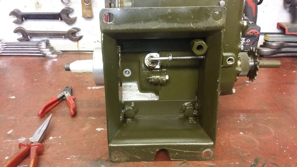
Crankcase drain valve as originally fitted.
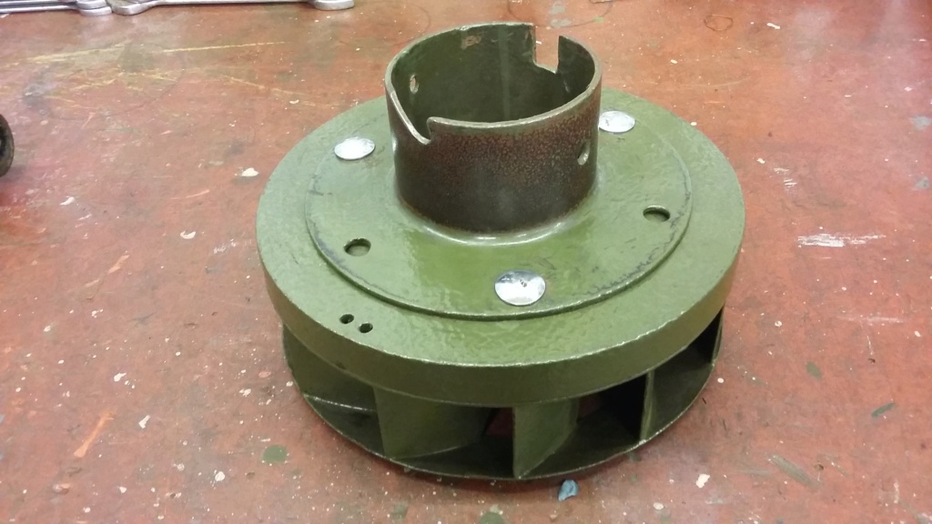
Latest Jowett’s flywheel with rope start modification.
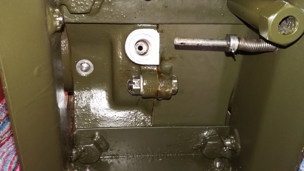
Ball valve seating with valve removed.

Ball valve removed. Lever is pulled to the right which in turn allows the ball to move off its seating.
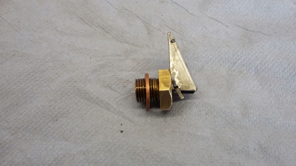
Valve with thick washer, this caused the ball not to seat correctly.
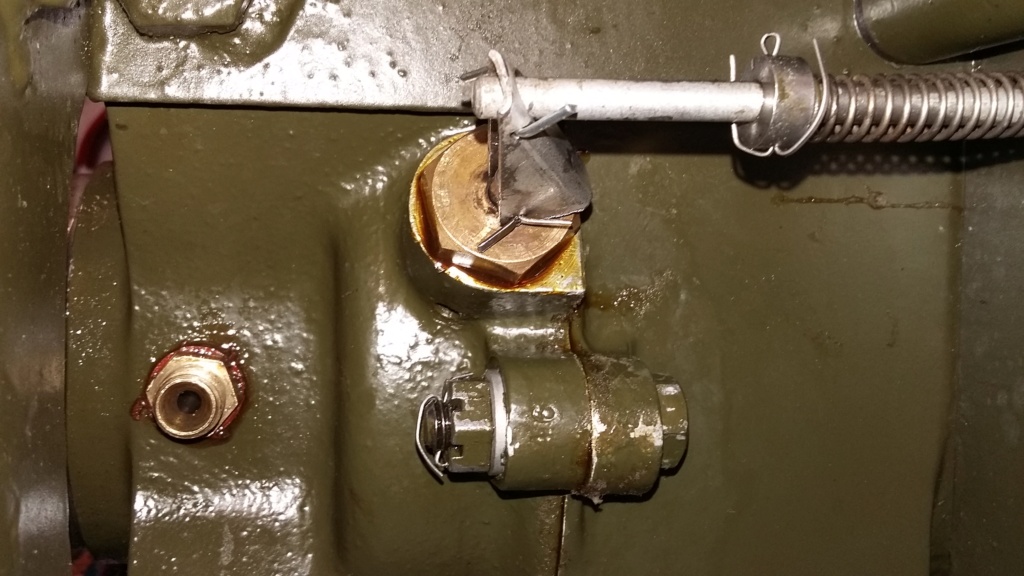
Valve reassembled. Note the lever linkage and the hole in the casting which is the vent. The other small coupler is for the bearing drain pipe.
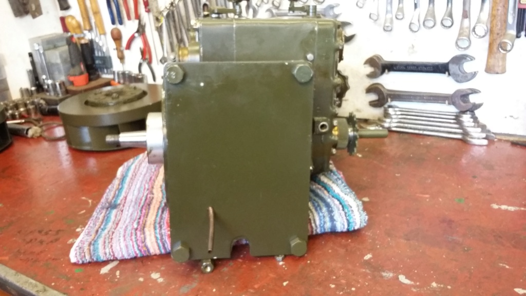
Bearing drain pipe and the base plate refitted. The base plate ensures nothing can be accessed without fully disassembling everything!
I’ll leave this update here and will continue with how well the engine testing proceeded once everything was back together, in a future post. However this will be delayed once again, as I have other commitments for a couple of weeks.
Neil.
Having noted that it has been over a month since my last update, I felt it was only right and proper for those who have been following this restoration thread and have engaged with it, through their comments and useful suggestions, that I at least let you know what I have been up to.
First let me say I haven’t stopped working towards completing this restoration, nor have I lost interest in it. In fact I had hoped to have it finished sufficiently to be able to display it, either running or as a static exhibit, at a 40’s event to be held at a preserved railway. Unfortunately with the ongoing conflict in Ukraine, this event has been cancelled. I must admit this did take away the impetus to finish the set within a fixed time scale. This coupled with storm damage to my roof at home which required my attention, allowed me the time to reflect on how best to proceed with the restoration. I have therefore decided to continue to assess and hopefully improve how well the engine is running and ensure that I get it performing as well as I can, before assembling the engine back into the rest of the set.
This has meant that since my last post I have effectively been performing the well-known stationary engine dance routine “The Restoration Waltz”. One step forwards, backwards, sideways and all back together again. In other words I have been attempting to resolve issues with the running of the engine. This has necessitated a certain amount of revisiting areas of engine rebuild that had been thought to have been completed.
As previously mentioned, I did achieve getting the engine to actually run, using a carburettor float bowl full of fuel. However this wasn’t easily achieved, with starting proving difficult, even though I have been able to fit the flywheel off the recently acquired Jowett which has been adapted to have a rope start capability. This allowed for easier turning of the engine, than could be achieved by flicking the flywheel over by hand and was less dangerous to the fingers.
Having run the engine several times, it was apparent that the engine seemed to lack the ability to pick up any speed, certainly nowhere near the operating speed of 3000 rpm required to produce the correct electrical output.
After running, I noted that there was a pool of oily fluid which had accumulated under the engine. As this is a two stroke engine and the oil wasn’t from the auxiliary drive, this can have only come from the two stroke mixture in the crankcase. With the engine mounted on the sub frame it is not possible to examine crankcase without taking everything apart again, separating engine from its mounting. The crankcase joint looked oil tight, so it had to be coming from somewhere else. There were two possibilities, first is a drain from the bearing housing, which seemed dry and is piped further away. The second is the crankcase drain valve, used to clear the crankcase if it becomes flooded. The valve is a sprung loaded ball bearing which is released by pulling an operating rod which eases the pressure on the ball bearing, allowing any accumulated mixture to be expelled from the crankcase by turning the engine over, using crankcase pressure to blow the mixture out through the valve drain hole.
When I rebuilt the engine I fitted a thick copper washer under the base of the valve which on reflection was totally unnecessary, as the seal is the ball bearing in its seat and as there is an open drain hole in the casting above the valve base, there is no point trying to seal the threaded boss. However by fitting the washer, I had unintentionally increased the length of the assembly which resulted in the ball valve failing to be held properly closed. I therefore removed the washer and reassembled everything as it should be and noted that there was now an element of free play in the valve mechanism, proving it was now seating correctly.

Crankcase drain valve as originally fitted.

Latest Jowett’s flywheel with rope start modification.

Ball valve seating with valve removed.

Ball valve removed. Lever is pulled to the right which in turn allows the ball to move off its seating.

Valve with thick washer, this caused the ball not to seat correctly.

Valve reassembled. Note the lever linkage and the hole in the casting which is the vent. The other small coupler is for the bearing drain pipe.

Bearing drain pipe and the base plate refitted. The base plate ensures nothing can be accessed without fully disassembling everything!
I’ll leave this update here and will continue with how well the engine testing proceeded once everything was back together, in a future post. However this will be delayed once again, as I have other commitments for a couple of weeks.
Neil.
neil (LE)- A credit to the forum

- Posts : 399
Join date : 2012-03-21
Age : 68
Location : N/W Kent
 Re: Scott Generating Set Restoration (Continues)
Oh Yessss! a good read for on holiday next week 
Nice work and in focus pictures too
Nice work and in focus pictures too

Andywaters- Life Member

- Posts : 609
Join date : 2021-09-15
Age : 66
 Re: Scott Generating Set Restoration (Continues)
Engine Testing Continues
Having returned home, I've been able to continue with the testing of the engine. In an attempt to understand if the rebuilt engine is basically sound, I have decided to utilise the carburettor and magneto from another known working unit, as part of an elimination process. I know it is usually best practise to change one item at a time but I am keen to understand if the engine is viable or if it will need to be stripped down once more, for further assessment. In my ownership this engine has never been run properly for more than a few seconds. Even then it has been difficult to start, so I was beginning to become concerned about the compression status of the engine. Being a two stroke there are two separate compression figures which need to be considered, the cylinder and the crankcase. I have re-tested the cylinder compression using the rope start to turn the engine over and I believe the figure of 91 psi achieved should be sufficient for this type and age of engine. However I am not familiar with how to measure crankcase compression or what an acceptable reading would be. There is the potential to use the crankcase drain valve threaded boss with an adaptor to connect the gauge but I haven't so far taken this any further but I would be interested to hear what others think about this as an idea and what figure to expect.
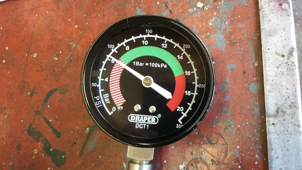
Cylinder Compression figure, 91 psi. Hopefully an acceptable reading?
My intention of using the known good substitute parts was to hopefully eliminate my concerns over the compression issues. If I could achieve satisfactory running of the engine using these items then I would be able to continue to investigate the setup, without worrying too much about the actual engine build status, especially the crankshaft seals.
With the items changed over and set up correctly, I am pleased to confirm that I have achieved a successful run of the engine for over 1 minute. It ran up to a high speed and the governor operated on the throttle to control the speed. I wasn't able to confirm the actual speed but it was certainly within the expected operating range of 2000 - 3000 rpm which is quite exhilarating when the engine is sitting free standing on the workbench. The fact the engine ran at this speed without moving around or vibrating too severely indicates how well balanced the engine is.
Now comes the scary bit, I will try and attach a You Tube video of the engine running. If successful it should appear here!
I will leave this here for now and see if the video link works.
The next stage will be to undertake a process of elimination until I am able to identify a working combination, utilising as many of the original components as possible.
Neil.
Having returned home, I've been able to continue with the testing of the engine. In an attempt to understand if the rebuilt engine is basically sound, I have decided to utilise the carburettor and magneto from another known working unit, as part of an elimination process. I know it is usually best practise to change one item at a time but I am keen to understand if the engine is viable or if it will need to be stripped down once more, for further assessment. In my ownership this engine has never been run properly for more than a few seconds. Even then it has been difficult to start, so I was beginning to become concerned about the compression status of the engine. Being a two stroke there are two separate compression figures which need to be considered, the cylinder and the crankcase. I have re-tested the cylinder compression using the rope start to turn the engine over and I believe the figure of 91 psi achieved should be sufficient for this type and age of engine. However I am not familiar with how to measure crankcase compression or what an acceptable reading would be. There is the potential to use the crankcase drain valve threaded boss with an adaptor to connect the gauge but I haven't so far taken this any further but I would be interested to hear what others think about this as an idea and what figure to expect.

Cylinder Compression figure, 91 psi. Hopefully an acceptable reading?
My intention of using the known good substitute parts was to hopefully eliminate my concerns over the compression issues. If I could achieve satisfactory running of the engine using these items then I would be able to continue to investigate the setup, without worrying too much about the actual engine build status, especially the crankshaft seals.
With the items changed over and set up correctly, I am pleased to confirm that I have achieved a successful run of the engine for over 1 minute. It ran up to a high speed and the governor operated on the throttle to control the speed. I wasn't able to confirm the actual speed but it was certainly within the expected operating range of 2000 - 3000 rpm which is quite exhilarating when the engine is sitting free standing on the workbench. The fact the engine ran at this speed without moving around or vibrating too severely indicates how well balanced the engine is.
Now comes the scary bit, I will try and attach a You Tube video of the engine running. If successful it should appear here!
I will leave this here for now and see if the video link works.
The next stage will be to undertake a process of elimination until I am able to identify a working combination, utilising as many of the original components as possible.
Neil.
neil (LE)- A credit to the forum

- Posts : 399
Join date : 2012-03-21
Age : 68
Location : N/W Kent
 Re: Scott Generating Set Restoration (Continues)
Great work, quite something to hear one running at rated speed, had mine throttled back (via adjusting the throttle arms on the governor spindle) to about 800rpm.
StuartTurnerSteve- Life Member

- Posts : 534
Join date : 2020-01-02
 Re: Scott Generating Set Restoration (Continues)
Sounds smooth! Don't know too much about 2 strokes but consider the crankcase to be a chamber that the fuel mix passes through? and therefore wouldn't contain a high pressure as such. As I see it as the piston comes down it's displacement causes the mix to get pushed into the combustion chamber so there is no great restriction - so little pressure.
Alan
Alan
Alanengine- A credit to the forum

- Posts : 461
Join date : 2020-11-21
 Re: Scott Generating Set Restoration (Continues)
Sounds and looks wonderful. Great job Neil.
_________________
Regards Paul
Tha can alus tell a Yorkshireman - but tha can't tell him much.

Woodsman- Admin
- Posts : 2815
Join date : 2014-08-24
Age : 73
Location : God's own county
 Re: Scott Generating Set Restoration (Continues)
IIRC, The PAB are a bit special being loop scavenged. So have a boost port across from the exhaust port, this was used by MZ with the Walter Kaden expansion chamber.
StuartTurnerSteve- Life Member

- Posts : 534
Join date : 2020-01-02
 Re: Scott Generating Set Restoration (Continues)
Thanks all, I'm not out of the woods yet but at least I have a good solid base to work from.
Alan you are correct in saying the fuel mixture is introduced via the crankcase. However to force it up into the cylinder, the charge is compressed as the piston descends, until the port is opened when the mixture rushes into the cylinder to be compressed as the piston rises. Therefore to achieve a good charge of fuel there needs to be a reasonable pressure built up in the crankcase prior to the port opening. This is why there needs to be a good seal around the crankcase and the crankshaft bearings to avoid pressure leakage. This I believe was my initial mistake, when I introduced the washer on the drain valve as that caused the ball valve not to seat properly which resulted in a loss of crankcase compression. This may have caused the difficulty in starting and poor running once it did start. After I removed the washer and achieved a good seal on the valve, the engine has run well and there is no indication of the oily leak which existed before. I am still interested to see if the crankcase pressure can be measured but I will most probably use the latest engine I have acquired to experiment on, rather than risk this unit.
Steve, yes I believe you do remember correctly. I understand the PAB does use the loop scavenge principle, some say they were the first manufacturer to do so. Certainly they pre-dated other companies such as MZ who claimed it as their own. I must admit I will have to look up the Walter Kaden expansion chamber, as I am not familiar with it.
Hopefully more to come...….
Neil.
neil (LE)- A credit to the forum

- Posts : 399
Join date : 2012-03-21
Age : 68
Location : N/W Kent
 Re: Scott Generating Set Restoration (Continues)
Counting my chickens too early?
Having successfully run the engine up to full operating speed, I was feeling quite satisfied with the progress on the engine and was looking forward to progressing to the next stage of the restoration. Unfortunately my smug feeling was to prove to be short lived. I couldn't resist running the engine up for a longer test run, by continuously topping up the float bowl. Everything was running smoothly when the engine suddenly cut out and slowly came to a halt and then refused to restart.
Basic examination confirmed the engine was free to turn over and compression was still apparent. Unfortunately further delving indicated there was a lack of spark. I had been using the magneto from the Jowett set as a known working unit, as part of my fault diagnosis process. The Jowett set had been used and run continuously for over an hour in the past. However it had always been a difficult starter which may have been indicative of a weak spark at starting speeds, even though it has the impulse unit.
Further investigation and testing proved the H.T. winding was open circuit. I am now wondering if there was already a break in the secondary windings which was arcing across internally, to maintain a weak spark at the plug. With the long running sessions, it is thought this has finally broken down the coil windings through spark erosion, such that the spark can no longer jump the gap in the internal windings.

The Jowett coil being tested and indicating as open circuit.
As I am fortunate enough to have more than one unit, I have been able to test the magnetos from the other engines. Unfortunately the Jowett magneto was not the only failure. The magneto which came with the latest Scott engine also tested open circuit and even though the engine was sold as working, I have never seen it running. If it did run, then the spark must be jumping internally in the same way as the Jowett one.

Latest Scott engine magneto, unfortunately also testing open circuit.
Of the other two magnetos only one is the correct screened military style, which is the one I had originally been using to test the running of the set. It was due to difficult starting and poor running that I substituted the Jowett one. The coil on this one seems to test correctly, although the magneto didn't seem to produce a good consistent spark. The coil on this unit looks different from the others, possibly indicating it has been rewound in the past and may not be as good as an original coil. The final magneto in the collection also tested as having a good secondary coil but is not fitted with the metal shielded cap. This unfortunately means the H.T. output tab on the coil, is in a different location and does not align with the shielded cap cover which on the face of it means the two types are not directly interchangeable parts. I will need to undertake further investigation to see if the non-shielded type of coil can be adapted to fit with the shielded cap.

Original magneto's coil testing OK with a reading of 7K ohms. Is this an original or a replacement re-wound coil?
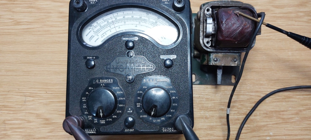
The final coil to be tested reads OK at 5.75K ohms. Note the location of the output contact which could prove difficult to adapt to the shielded cover.
The other component I am considering with regard to the poor / inconsistent spark is the condenser or capacitor. I have removed them from all of the magnetos, with some showing signs of age with the sealant holding the component inside breaking down into a sticky residue. Others seem to have had the internal capacitor replaced with more modern components. Some of the capacitors when tested on a meter capable of direct reading capacitor values, read open circuit, obviously indicating a faulty unit. Others indicate a capacitor value but they all give a different reading, so I might as well change them all out. I have two basic options, buy replacement components from the stationary engine spares suppliers market or fit my own capacitors within the original casings. The second option would prove cheaper and is relatively easy to achieve but I would be interested if anyone knows what the ratings of the component should be in terms of capacitance, operating voltage and tolerance.
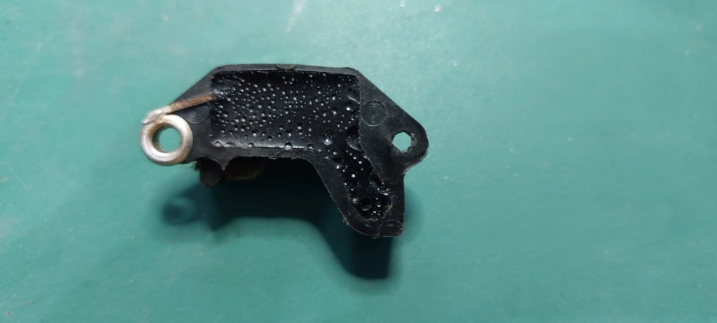
What the condenser underside should look like.
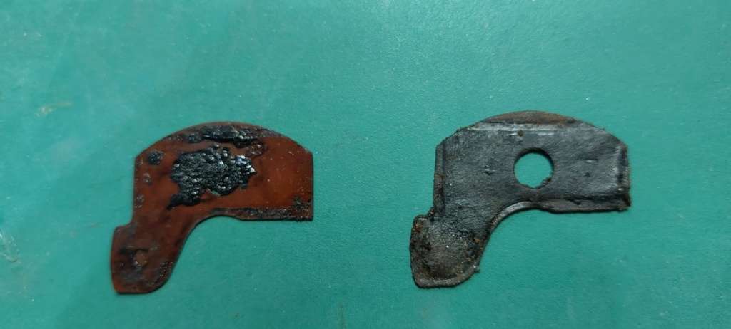
What the degraded bases looked like.

An original wax coated condenser from the inside of one of the cases. Almost guaranteed to have either failed or have change its characteristics, in terms of values.
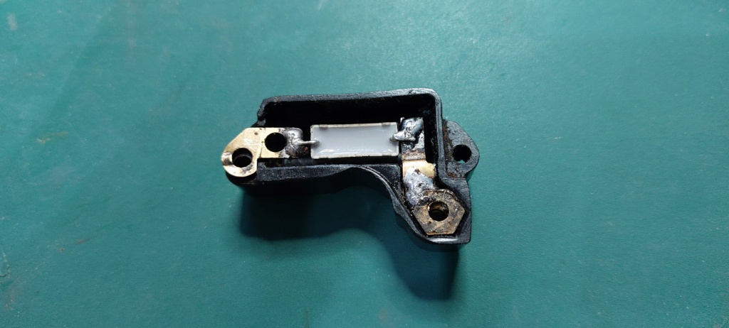
A more modern component in use in the later style of condenser package.
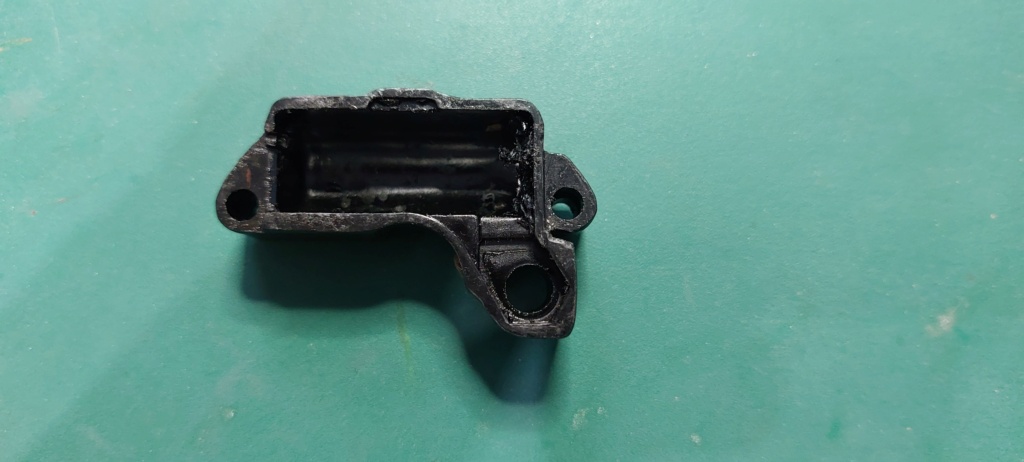
The empty case in which a replacement component part could be fitted. I just need to research the correct values required.
I have been fortunate in locating a further military style Wico magneto. Although not the exact same model and is a reverse rotation type, if I'm lucky it may have a good coil. If not it should still provide other useful spares.
I'll let you know how I get on....
Neil.
Having successfully run the engine up to full operating speed, I was feeling quite satisfied with the progress on the engine and was looking forward to progressing to the next stage of the restoration. Unfortunately my smug feeling was to prove to be short lived. I couldn't resist running the engine up for a longer test run, by continuously topping up the float bowl. Everything was running smoothly when the engine suddenly cut out and slowly came to a halt and then refused to restart.
Basic examination confirmed the engine was free to turn over and compression was still apparent. Unfortunately further delving indicated there was a lack of spark. I had been using the magneto from the Jowett set as a known working unit, as part of my fault diagnosis process. The Jowett set had been used and run continuously for over an hour in the past. However it had always been a difficult starter which may have been indicative of a weak spark at starting speeds, even though it has the impulse unit.
Further investigation and testing proved the H.T. winding was open circuit. I am now wondering if there was already a break in the secondary windings which was arcing across internally, to maintain a weak spark at the plug. With the long running sessions, it is thought this has finally broken down the coil windings through spark erosion, such that the spark can no longer jump the gap in the internal windings.

The Jowett coil being tested and indicating as open circuit.
As I am fortunate enough to have more than one unit, I have been able to test the magnetos from the other engines. Unfortunately the Jowett magneto was not the only failure. The magneto which came with the latest Scott engine also tested open circuit and even though the engine was sold as working, I have never seen it running. If it did run, then the spark must be jumping internally in the same way as the Jowett one.

Latest Scott engine magneto, unfortunately also testing open circuit.
Of the other two magnetos only one is the correct screened military style, which is the one I had originally been using to test the running of the set. It was due to difficult starting and poor running that I substituted the Jowett one. The coil on this one seems to test correctly, although the magneto didn't seem to produce a good consistent spark. The coil on this unit looks different from the others, possibly indicating it has been rewound in the past and may not be as good as an original coil. The final magneto in the collection also tested as having a good secondary coil but is not fitted with the metal shielded cap. This unfortunately means the H.T. output tab on the coil, is in a different location and does not align with the shielded cap cover which on the face of it means the two types are not directly interchangeable parts. I will need to undertake further investigation to see if the non-shielded type of coil can be adapted to fit with the shielded cap.

Original magneto's coil testing OK with a reading of 7K ohms. Is this an original or a replacement re-wound coil?

The final coil to be tested reads OK at 5.75K ohms. Note the location of the output contact which could prove difficult to adapt to the shielded cover.
The other component I am considering with regard to the poor / inconsistent spark is the condenser or capacitor. I have removed them from all of the magnetos, with some showing signs of age with the sealant holding the component inside breaking down into a sticky residue. Others seem to have had the internal capacitor replaced with more modern components. Some of the capacitors when tested on a meter capable of direct reading capacitor values, read open circuit, obviously indicating a faulty unit. Others indicate a capacitor value but they all give a different reading, so I might as well change them all out. I have two basic options, buy replacement components from the stationary engine spares suppliers market or fit my own capacitors within the original casings. The second option would prove cheaper and is relatively easy to achieve but I would be interested if anyone knows what the ratings of the component should be in terms of capacitance, operating voltage and tolerance.

What the condenser underside should look like.

What the degraded bases looked like.

An original wax coated condenser from the inside of one of the cases. Almost guaranteed to have either failed or have change its characteristics, in terms of values.

A more modern component in use in the later style of condenser package.

The empty case in which a replacement component part could be fitted. I just need to research the correct values required.
I have been fortunate in locating a further military style Wico magneto. Although not the exact same model and is a reverse rotation type, if I'm lucky it may have a good coil. If not it should still provide other useful spares.
I'll let you know how I get on....
Neil.
neil (LE)- A credit to the forum

- Posts : 399
Join date : 2012-03-21
Age : 68
Location : N/W Kent
 Re: Scott Generating Set Restoration (Continues)
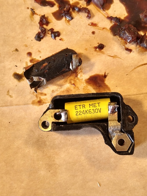
Neil, so near yet so far!
I changed the condenser on the Wico A fitted to my JAP. It measured low resistance (can't remember what) but it should read a high value - a low figure suggests a leakage.
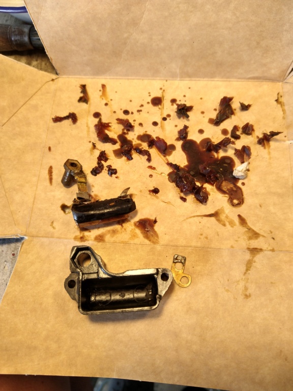
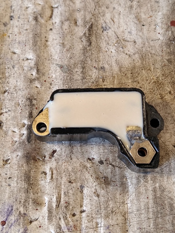
I dug out the old potting material which looked like bitumen and re potted the new cap with a low viscosity silicone product which was easily pourable. I used this as I had this in stock, if I hadn't I would have used a neutral cure product from a cartridge and 'worked' it into the cavity.
Cap value was .22uf.
Alan
Alanengine- A credit to the forum

- Posts : 461
Join date : 2020-11-21
 Re: Scott Generating Set Restoration (Continues)
Alan, as you say "so near, yet so far". Frustrating is the polite word I would use for it but at least I have identified the issue before it was all back together again. This was my intention when I decided to undertake some more extensive bench testing prior to re-assembling the engine back into chassis.
Your approach to replacing the capacitor is exactly what I had in mind to do. If mine turn out as good as your one looks, I will be very happy. However before I actually proceed, I was wondering how you arrived at the value and type for the replacement capacitor.
Of the four I have tested, I have recorded a wide range of values.
1 x 0.045uF New style moulding, not taken apart
1 x 0.096uF Old style moulding, with new type of capacitor marked o.1uF
1 x 0.158uF New style moulding not taken apart
1 x 2.7uF Old style moulding with wax coated capacitor with no markings.
So far I have not identified any reference material as to what the design value for the capacitor was.
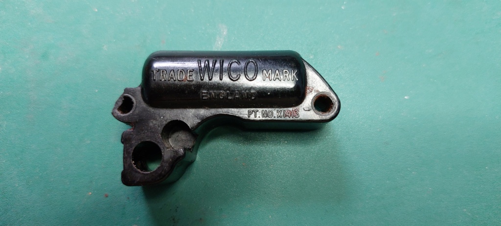
The "old style" moulding, marked Wico.
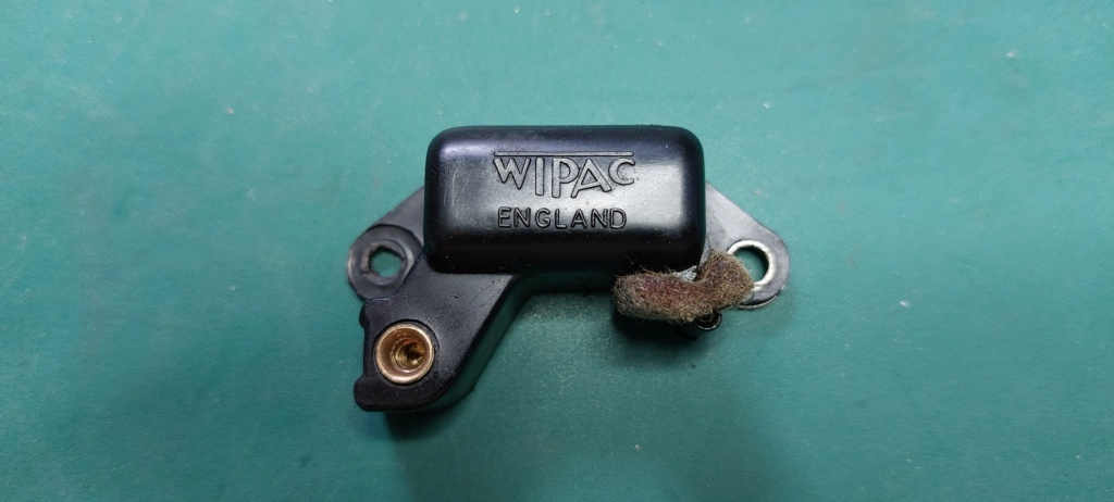
The "new style" moulding, marked Wipac.

New type of capacitor in the "old style" moulding. Capacitor value marked as O.1uF tested as 0.096uF, well within tolerance.
Hopefully more progress soon.....
Neil.
Your approach to replacing the capacitor is exactly what I had in mind to do. If mine turn out as good as your one looks, I will be very happy. However before I actually proceed, I was wondering how you arrived at the value and type for the replacement capacitor.
Of the four I have tested, I have recorded a wide range of values.
1 x 0.045uF New style moulding, not taken apart
1 x 0.096uF Old style moulding, with new type of capacitor marked o.1uF
1 x 0.158uF New style moulding not taken apart
1 x 2.7uF Old style moulding with wax coated capacitor with no markings.
So far I have not identified any reference material as to what the design value for the capacitor was.

The "old style" moulding, marked Wico.

The "new style" moulding, marked Wipac.

New type of capacitor in the "old style" moulding. Capacitor value marked as O.1uF tested as 0.096uF, well within tolerance.
Hopefully more progress soon.....
Neil.
neil (LE)- A credit to the forum

- Posts : 399
Join date : 2012-03-21
Age : 68
Location : N/W Kent
 Re: Scott Generating Set Restoration (Continues)
From my investigation it would seem the value is not terribly critical, anything between .1 and .33uf would be fine. The working voltage should be at least 400, the yellow one that I used is of the polyester type used when re capping my valve radios.
Alan
Alan
Alanengine- A credit to the forum

- Posts : 461
Join date : 2020-11-21
Page 10 of 13 •  1, 2, 3 ... 9, 10, 11, 12, 13
 Similar topics
» Scott PAB Restoration
» Kubota diesel KND3
» Trolley for Villiers Mk15 wooden toolbox new pics 5-9-2016
» Petter generating set - might turn into a project
» Douglas FT35 generating set
» Kubota diesel KND3
» Trolley for Villiers Mk15 wooden toolbox new pics 5-9-2016
» Petter generating set - might turn into a project
» Douglas FT35 generating set
Page 10 of 13
Permissions in this forum:
You cannot reply to topics in this forum