Scott Generating Set Restoration (Continues)
+9
Robotstar5
nickh
RichieR
oldgit
Andrew1971
maryalice
blue cat
StuartTurnerSteve
Woodsman
13 posters
Page 2 of 13
Page 2 of 13 •  1, 2, 3, ... 11, 12, 13
 Re: Scott Generating Set Restoration (Continues)
Thanks Steve, I might see if I can temporarily attach some form of starting handle, don't think I'll be able to pull it over on the flywheel, not with the alternator directly coupled! I can imagine how frustrating it must have been at the I.F. rally when it didn't want to start. I must admit these engines are not known as the easiest starters.
Neil.
Neil.
neil (LE)- A credit to the forum

- Posts : 399
Join date : 2012-03-21
Age : 68
Location : N/W Kent
 Re: Scott Generating Set Restoration (Continues)
Mine would flood quite easily IIRC, I was also restricting it more than it would have liked to.
Though it sat quite well at 800rpm when it was going, ran so cold you could put your hand on the 1st expansion chamber fine.
Though it sat quite well at 800rpm when it was going, ran so cold you could put your hand on the 1st expansion chamber fine.
StuartTurnerSteve- Life Member

- Posts : 534
Join date : 2020-01-02
 Re: Scott Generating Set Restoration (Continues)
The dashpot oil brings back memories, as an apprentice in the 70's, one of my jobs was to go round checking and topping up the dashpots.
_________________
Stuart
Robotstar5- Life Member

- Posts : 1109
Join date : 2018-09-25
 Re: Scott Generating Set Restoration (Continues)
Thanks gentlemen for your feedback. Stuart I hope your apprenticeship in this field, means you are the go to man when I need information and assistance, when setting up the new starter switch!
Alternator Regulator.
As part of the canopy strip down, the regulator unit for the alternator was removed and set aside until I was able to check it over. The regulator is a multi-stepped variable resistor which is in series with the output of the exciter. This adjusts the current flow from the exciter generator through the field coils in the alternator, thereby altering the voltage output of the alternator. The resistor is made up of a number of open wound ceramic resistor with 10 tap-off points, providing this number of discreet values of resistance. Being series wound, any break in the resistance wire windings would render the regulator useless from the break point onwards. The worst place for a resistor to fail would be at the first tap-off point, as all settings utilise that first resistor. Therefore if there is a good place for a failure, it would be the last tap point, as that would only affect the final setting, all other positions would continue to operate correctly.
It was with this in mind that I examined the unit, hoping for no breakages in the resistance windings, especially the early ones. First impressions were not good, the resistor coils looked to be in poor condition, being covered with verdigris. Therefore it was with low expectations I tested the unit and I wasn't surprised when initially it proved open circuit. However there was something wrong, the first position should be a direct connection bypassing the resistors. Further checking proved the problem was purely corrosion on the wiper. Once cleaned the reading went from open circuit to short circuit which was correct. Further testing proved all positions provided readings which seemed to correspond to what might be expected. The unit test correct for resistance and will hopefully work but I will not be certain until it is operating in circuit when it needs to be able to continuously pass up to 1.5 amps. Time will tell, as with the rest of the electrics.
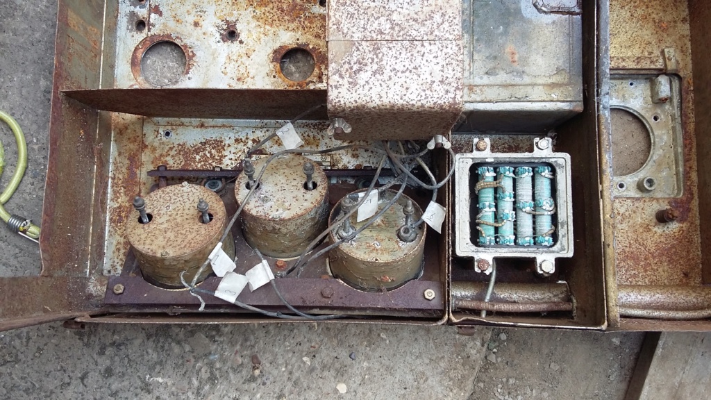
Regulator as fitted to the canopy.
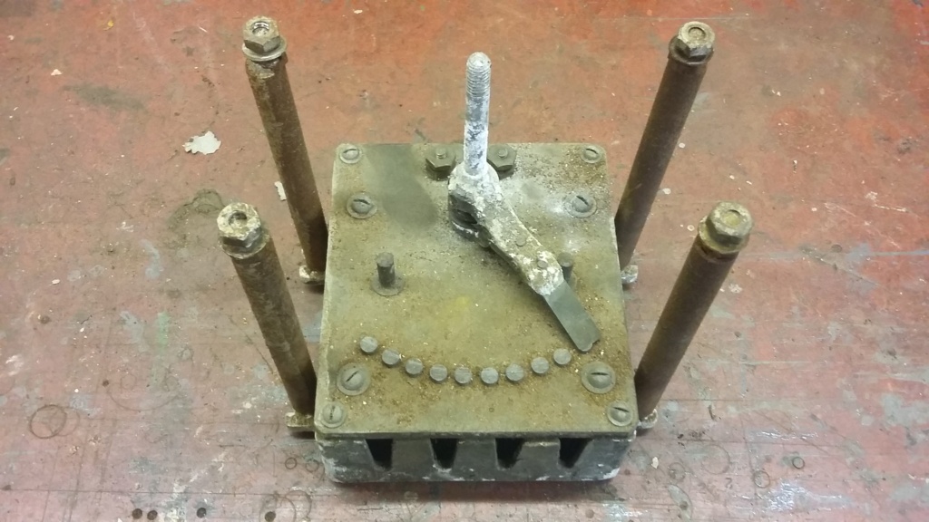
The dirt and corrosion on the wiper and contact studs which caused the open circuit reading and concerns when initially testing the unit.
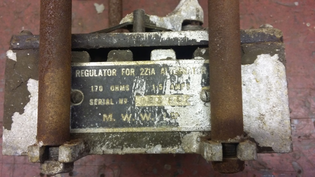
Overall state of the unit and specification plate.
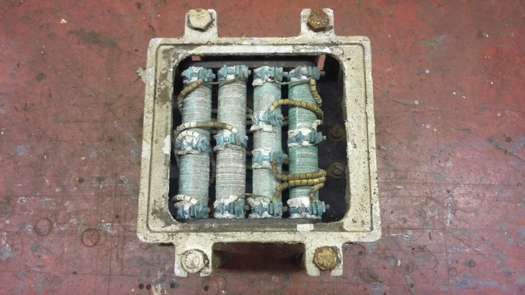
The resistors showing the tap-off points, also note the ceramic bead insulators.

Position one, correctly indicating short circuit.
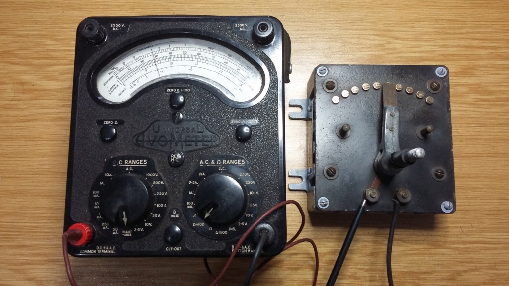
Mid position reading 50 ohms.

Top position correctly reading approximately 160 ohms as compared with 170 ohms on spec. plate. Proving complete resistor bank is viable, just needs to be tested under load.

Re-assembled with the housing in primer and the spec. plate cleaned up.
Alternator Regulator.
As part of the canopy strip down, the regulator unit for the alternator was removed and set aside until I was able to check it over. The regulator is a multi-stepped variable resistor which is in series with the output of the exciter. This adjusts the current flow from the exciter generator through the field coils in the alternator, thereby altering the voltage output of the alternator. The resistor is made up of a number of open wound ceramic resistor with 10 tap-off points, providing this number of discreet values of resistance. Being series wound, any break in the resistance wire windings would render the regulator useless from the break point onwards. The worst place for a resistor to fail would be at the first tap-off point, as all settings utilise that first resistor. Therefore if there is a good place for a failure, it would be the last tap point, as that would only affect the final setting, all other positions would continue to operate correctly.
It was with this in mind that I examined the unit, hoping for no breakages in the resistance windings, especially the early ones. First impressions were not good, the resistor coils looked to be in poor condition, being covered with verdigris. Therefore it was with low expectations I tested the unit and I wasn't surprised when initially it proved open circuit. However there was something wrong, the first position should be a direct connection bypassing the resistors. Further checking proved the problem was purely corrosion on the wiper. Once cleaned the reading went from open circuit to short circuit which was correct. Further testing proved all positions provided readings which seemed to correspond to what might be expected. The unit test correct for resistance and will hopefully work but I will not be certain until it is operating in circuit when it needs to be able to continuously pass up to 1.5 amps. Time will tell, as with the rest of the electrics.

Regulator as fitted to the canopy.

The dirt and corrosion on the wiper and contact studs which caused the open circuit reading and concerns when initially testing the unit.

Overall state of the unit and specification plate.

The resistors showing the tap-off points, also note the ceramic bead insulators.

Position one, correctly indicating short circuit.

Mid position reading 50 ohms.

Top position correctly reading approximately 160 ohms as compared with 170 ohms on spec. plate. Proving complete resistor bank is viable, just needs to be tested under load.

Re-assembled with the housing in primer and the spec. plate cleaned up.
neil (LE)- A credit to the forum

- Posts : 399
Join date : 2012-03-21
Age : 68
Location : N/W Kent
 Re: Scott Generating Set Restoration (Continues)
Sounds promising!
Alan
Alan
Alanengine- A credit to the forum

- Posts : 461
Join date : 2020-11-21
 Re: Scott Generating Set Restoration (Continues)
Cheers Alan, as you say it's promising, my only concern is if the coating of verdigris will cause hot spots on the windings, causing them to overheat under load and break, as I said time will tell. I believe the windings are too fragile to attempt to remove the verdigris, so I have no option but to try it as it is.
Nothing very exciting undertaken today but an important, if mundane task which needed to be completed before the engine is reassembled was taken on. As I mentioned previously, cleaning up parts for painting is sometimes left until the last moment, as it is not very stimulating and is easy to put off. The combination of lockdown and bad weather has limited the range of things which can be achieved so I took the opportunity to clean and prepare the flywheel for painting. Not having access to a blast cabinet, the flywheel had to be tackled using wire wheels and due to the attached fan blade design, a lot of use of hand tools, to clean between the blades.
Not exciting but essential and at least it's done and is now ready for the paint to be applied.
Hopefully more to come for those who are following progress.
Neil
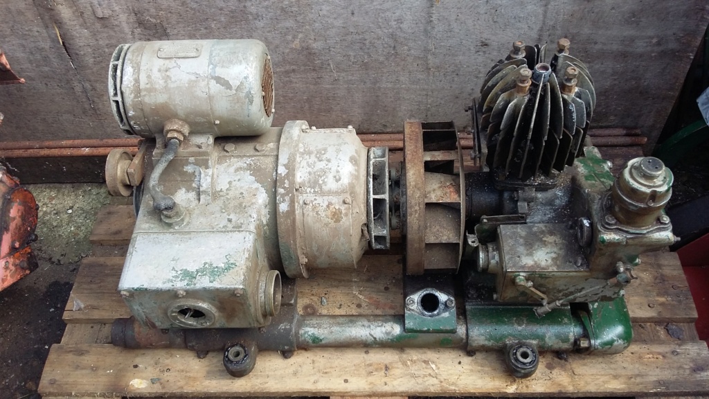

Condition of flywheel before disassembly, in need of some T.L.C.
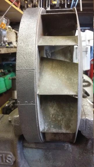
Flywheel crown cleaned up using wire wheels, just leaving the fan blades to be tackled by hand.
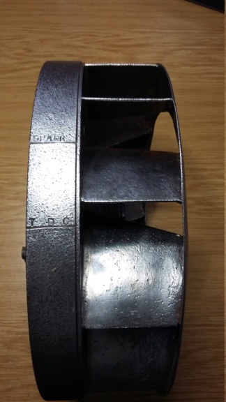
Flywheel finished, including fan blades.

Drive face.
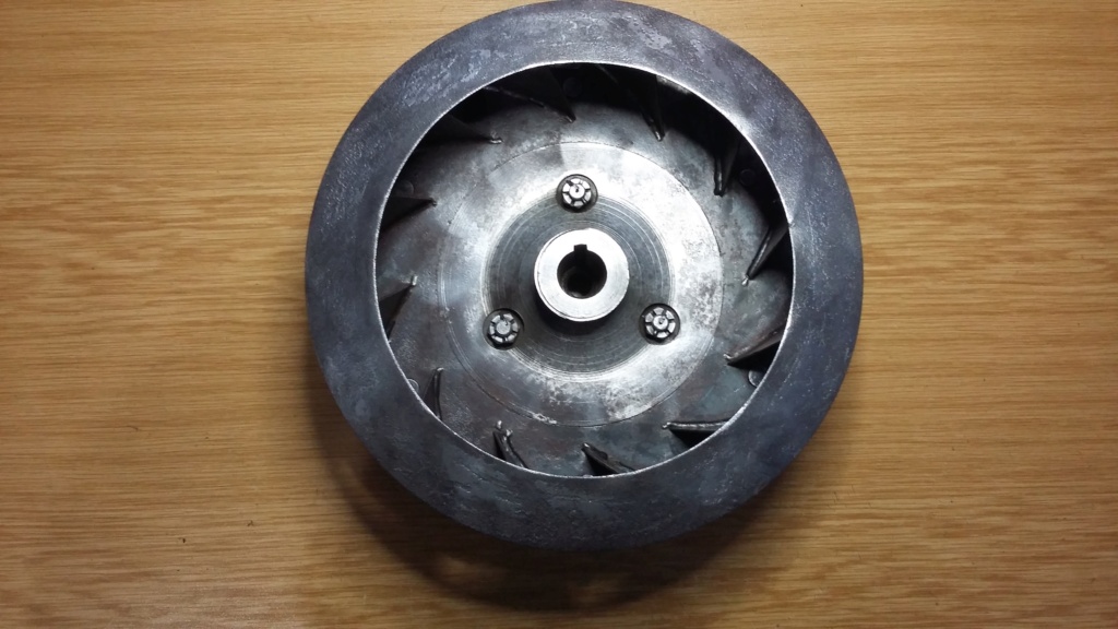
Fan side.
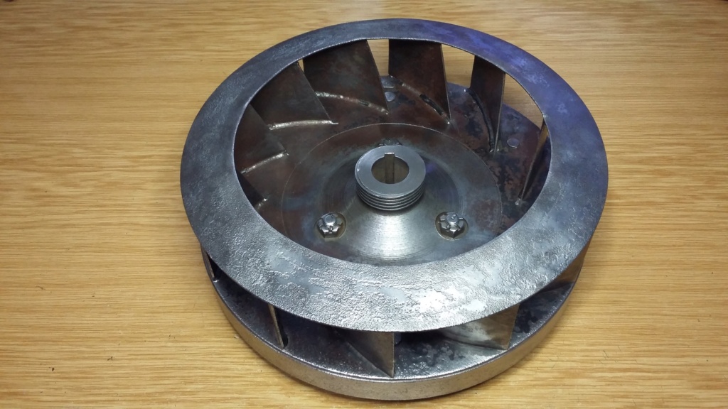
Overall view, paint to follow.
Nothing very exciting undertaken today but an important, if mundane task which needed to be completed before the engine is reassembled was taken on. As I mentioned previously, cleaning up parts for painting is sometimes left until the last moment, as it is not very stimulating and is easy to put off. The combination of lockdown and bad weather has limited the range of things which can be achieved so I took the opportunity to clean and prepare the flywheel for painting. Not having access to a blast cabinet, the flywheel had to be tackled using wire wheels and due to the attached fan blade design, a lot of use of hand tools, to clean between the blades.
Not exciting but essential and at least it's done and is now ready for the paint to be applied.
Hopefully more to come for those who are following progress.
Neil


Condition of flywheel before disassembly, in need of some T.L.C.

Flywheel crown cleaned up using wire wheels, just leaving the fan blades to be tackled by hand.

Flywheel finished, including fan blades.

Drive face.

Fan side.

Overall view, paint to follow.
neil (LE)- A credit to the forum

- Posts : 399
Join date : 2012-03-21
Age : 68
Location : N/W Kent
 Re: Scott Generating Set Restoration (Continues)
Last edited by mattblack on Tue Jan 19 2021, 19:13; edited 1 time in total (Reason for editing : resized photo)
_________________
Specialist in precision guesswork.

mattblack- Life Member

- Posts : 889
Join date : 2019-06-21
Location : Leicester, me duck...
 Re: Scott Generating Set Restoration (Continues)
That's amazing I can't imagine there are many of those out there to be found. In that box of tat, as you called it, you wouldn't happen to have an ignition control knob from one of these units to go with it. I'm missing one and would be interested if there was one available anywhere.
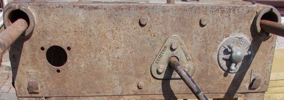
End panel minus Ignition control knob.

What it should fitted.

A complete unit out of set. The ignition one is the same, just different markings.
If anybody has one of these that they would be willing to part with, either type, please let me know.
Many thanks,
Neil

End panel minus Ignition control knob.

What it should fitted.

A complete unit out of set. The ignition one is the same, just different markings.
If anybody has one of these that they would be willing to part with, either type, please let me know.
Many thanks,
Neil
neil (LE)- A credit to the forum

- Posts : 399
Join date : 2012-03-21
Age : 68
Location : N/W Kent
 Re: Scott Generating Set Restoration (Continues)
M. W. W. Ltd is M. W. Woods Ltd of Colchester. They manufactured the alternator and associated equipment.
https://www.gracesguide.co.uk/Woods_of_Colchester
They are still in business today making ventilation fans as Flakt Woods, Mile End Colchester.
https://www.flaktgroup.com/uk/our-brands/woods/history/
https://www.gracesguide.co.uk/Woods_of_Colchester
They are still in business today making ventilation fans as Flakt Woods, Mile End Colchester.
https://www.flaktgroup.com/uk/our-brands/woods/history/
_________________
blue cat
blue cat- Life Member

- Posts : 1065
Join date : 2013-10-10
 Re: Scott Generating Set Restoration (Continues)
Thanks blue cat, could be useful if I need any information with regard to the alternator set up, they may still have some old documentation available.
Neil
Neil
neil (LE)- A credit to the forum

- Posts : 399
Join date : 2012-03-21
Age : 68
Location : N/W Kent
 Re: Scott Generating Set Restoration (Continues)
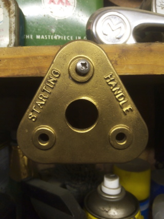
Sorry, can't help with the ignition knob. The starting handle plate came from ebay for £1 IIRC, I was looking through the listings for 'Stationary Engine' and just took a fancy to it.
_________________
Specialist in precision guesswork.

mattblack- Life Member

- Posts : 889
Join date : 2019-06-21
Location : Leicester, me duck...
 Re: Scott Generating Set Restoration (Continues)
It was worth checking you never know if you don't ask. Maybe someone else will have one tucked away in their collection, which they are willing to part with. I would be interested in your starting handle plate, if you are in the market to sell it on, as I have a free standing Scott which I could use it with. Send me a PM if you want to discuss further.
Thanks,
Neil.
Thanks,
Neil.
neil (LE)- A credit to the forum

- Posts : 399
Join date : 2012-03-21
Age : 68
Location : N/W Kent
 Re: Scott Generating Set Restoration (Continues)
You have a PM.
_________________
Specialist in precision guesswork.

mattblack- Life Member

- Posts : 889
Join date : 2019-06-21
Location : Leicester, me duck...
 Re: Scott Generating Set Restoration (Continues)
I have replied.
Neil
Neil
neil (LE)- A credit to the forum

- Posts : 399
Join date : 2012-03-21
Age : 68
Location : N/W Kent
 Re: Scott Generating Set Restoration (Continues)
mattblack wrote:You have a PM.
neil (LE) wrote:I have replied. Neil
How mysterious
_________________
Regards Paul
Tha can alus tell a Yorkshireman - but tha can't tell him much.

Woodsman- Admin
- Posts : 2815
Join date : 2014-08-24
Age : 73
Location : God's own county
 Re: Scott Generating Set Restoration (Continues)
Nothing mysterious, just PM ping pong, a game for all forums! 
neil (LE)- A credit to the forum

- Posts : 399
Join date : 2012-03-21
Age : 68
Location : N/W Kent
 Re: Scott Generating Set Restoration (Continues)
Some info on the set from Kim Siddorn.
https://www.wessexsec.org/wp-content/uploads/2020/01/July_2007.pdf
https://www.wessexsec.org/wp-content/uploads/2020/01/July_2007.pdf
StuartTurnerSteve- Life Member

- Posts : 534
Join date : 2020-01-02
 Re: Scott Generating Set Restoration (Continues)
StuartTurnerSteve wrote:Some info on the set from Kim Siddorn.
https://www.wessexsec.org/wp-content/uploads/2020/01/July_2007.pdf
Steve,
Are the Wessex newsletters still accessable, Kim gave me the website and I used to love reading them but I've lost the site.
He is one character that I miss, he turned up to a rally one Sunday, he'd been a Viking the day before and during the day he got me to put on his chainmail and carry his sword, the chainmail felt like I had a large child on my shoulders and I used the sword as a walking stick
Maryalice
maryalice- Life Member

- Posts : 1310
Join date : 2010-01-23
Age : 70
Location : Bedfordshire
 Re: Scott Generating Set Restoration (Continues)
Yes they have been uploaded to the website.
https://wessexsec.org/newsletters/
https://wessexsec.org/newsletters/
StuartTurnerSteve- Life Member

- Posts : 534
Join date : 2020-01-02
maryalice- Life Member

- Posts : 1310
Join date : 2010-01-23
Age : 70
Location : Bedfordshire
 Re: Scott Generating Set Restoration (Continues)
Having completed the game of PM ping pong, I can now resume the restoration update. This continues on an electrical theme, by looking at the exciter generator. For those who are unfamiliar with the generator set up, I thought I would provide some details of the alternator configuration. The main alternator does not self excite, so needs a separate generator, to supply current to the alternator field coils. The exciter is a DC generator producing 150 volts off load and 130 volts at 1.5 amps full load, at 3800 rpm. It is directly mounted onto the casing of the alternator and is driven off a pulley on the end of alternator shaft, via a belt to the exciter pulley. The pulley ratio is arranged to provide 3800 rpm at the exciter, from the 3000 rpm running speed of the alternator.
The exciter output cable was disconnected from the alternator connection box and the exciter removed from the alternator. It was checked over for any obvious damage or issues. The only area which was cause for concern following a visual inspection was the main output cable, this was badly perished and would need to be replaced. Careful disassembly allowed the bearings to be examined, all seemed fine, and the old grease was replaced with new. The perished cables were removed, with draw wires used to facilitate the new cable to be pulled in. Having blocked off all openings the unit was striped of paint and corrosion and then primed. Before going much further I would like to be able to undertake some basic static tests on the unit, as dynamic testing will require running it at 3800 rpm. Even then without the load of the alternator, it will not produce the full voltage, as the exciter works in series with the alternator field coils, without these in circuit, it will only produce about 20 volts. Any suggestions on undertaking some tests would be appreciated.
That's all for now, hopefully more to come...
Neil

Exciter mounted on the main alternator, as removed from unit.
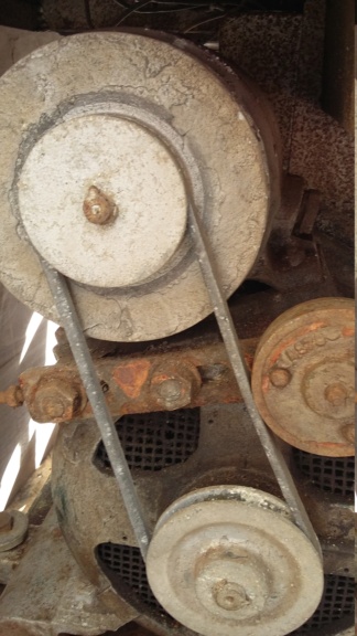
The pulley drive from the alternator to the exciter with tensioner jockey wheel.
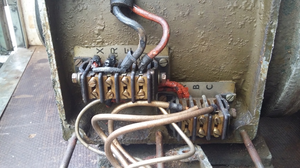
Alternator connection box, with the two main exciter cables to be disconnected.

Exciter separated from alternator. Note the condition of the main cable.

Exciter specification plate.
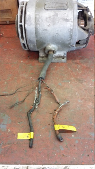
State of the main output wiring. Possibly in need of replacement!

Checking wiring routing, before disconnecting and removing anything.

Draw strings attached to old cables to facilitate renewing wiring.

End cover removed, first look inside. Dusty and dirty but no obvious damage.

Armature removed, looks to be in good condition. Would like to know of a basic way to test the windings, without access to a growler tester.
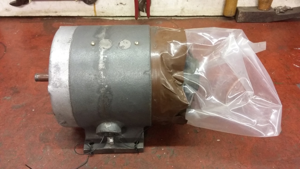

Exciter being prepared, ready for painting. All openings sealed off to protect internals and bearings from grit and dust.

Now in primer. Needs testing prior to final assembly, once I find a way to achieve this.
The exciter output cable was disconnected from the alternator connection box and the exciter removed from the alternator. It was checked over for any obvious damage or issues. The only area which was cause for concern following a visual inspection was the main output cable, this was badly perished and would need to be replaced. Careful disassembly allowed the bearings to be examined, all seemed fine, and the old grease was replaced with new. The perished cables were removed, with draw wires used to facilitate the new cable to be pulled in. Having blocked off all openings the unit was striped of paint and corrosion and then primed. Before going much further I would like to be able to undertake some basic static tests on the unit, as dynamic testing will require running it at 3800 rpm. Even then without the load of the alternator, it will not produce the full voltage, as the exciter works in series with the alternator field coils, without these in circuit, it will only produce about 20 volts. Any suggestions on undertaking some tests would be appreciated.
That's all for now, hopefully more to come...
Neil

Exciter mounted on the main alternator, as removed from unit.

The pulley drive from the alternator to the exciter with tensioner jockey wheel.

Alternator connection box, with the two main exciter cables to be disconnected.

Exciter separated from alternator. Note the condition of the main cable.

Exciter specification plate.

State of the main output wiring. Possibly in need of replacement!

Checking wiring routing, before disconnecting and removing anything.

Draw strings attached to old cables to facilitate renewing wiring.

End cover removed, first look inside. Dusty and dirty but no obvious damage.

Armature removed, looks to be in good condition. Would like to know of a basic way to test the windings, without access to a growler tester.


Exciter being prepared, ready for painting. All openings sealed off to protect internals and bearings from grit and dust.

Now in primer. Needs testing prior to final assembly, once I find a way to achieve this.
neil (LE)- A credit to the forum

- Posts : 399
Join date : 2012-03-21
Age : 68
Location : N/W Kent
 Re: Scott Generating Set Restoration (Continues)
Steve, thanks for the information. I do have a hard copy of that newsletter, although I cannot remember where or when I got it. It may have come with a set which came from mid-Devon. The other newsletter link you posted is restricted to members only.
Regards,
Neil.
Regards,
Neil.
neil (LE)- A credit to the forum

- Posts : 399
Join date : 2012-03-21
Age : 68
Location : N/W Kent
 Re: Scott Generating Set Restoration (Continues)
If it's like a car dynamo would it not run as a motor with some carefully applied DC?
Alan
Alan
Alanengine- A credit to the forum

- Posts : 461
Join date : 2020-11-21
 Re: Scott Generating Set Restoration (Continues)
Alan, I believe it might but I assume I would need something in the region of at least 100V D.C. to operate. I don't have an easy way to produce this. Any suggestions?
Neil
Neil
neil (LE)- A credit to the forum

- Posts : 399
Join date : 2012-03-21
Age : 68
Location : N/W Kent
 Re: Scott Generating Set Restoration (Continues)
Variac and rectifier?
Alan
Alan
Alanengine- A credit to the forum

- Posts : 461
Join date : 2020-11-21
Page 2 of 13 •  1, 2, 3, ... 11, 12, 13
 Similar topics
» Scott PAB Restoration
» Kubota diesel KND3
» Trolley for Villiers Mk15 wooden toolbox new pics 5-9-2016
» Petter generating set - might turn into a project
» Douglas FT35 generating set
» Kubota diesel KND3
» Trolley for Villiers Mk15 wooden toolbox new pics 5-9-2016
» Petter generating set - might turn into a project
» Douglas FT35 generating set
Page 2 of 13
Permissions in this forum:
You cannot reply to topics in this forum
