Scott Generating Set Restoration (Continues)
+9
Robotstar5
nickh
RichieR
oldgit
Andrew1971
maryalice
blue cat
StuartTurnerSteve
Woodsman
13 posters
Page 3 of 13
Page 3 of 13 •  1, 2, 3, 4 ... 11, 12, 13
 Re: Scott Generating Set Restoration (Continues)
Possibly, or a 110v plant transformer and rectifier. Even so I'm not 100% certain it is wired in the same way as a dynamo, so might not work anyway. Unless someone is able to confirm, I don't really want to apply voltage and risk the windings.
Neil
Neil
neil (LE)- A credit to the forum

- Posts : 399
Join date : 2012-03-21
Age : 68
Location : N/W Kent
 Re: Scott Generating Set Restoration (Continues)
Having recently mentioned the ignition and the mixture controls on the end of the canopy, the ignition one being missing on this example, I thought I would take a look at how these are constructed. Considering that these generating sets were produced to a War office contract, they seem to have been built to a high standard and not down to a price. Perhaps this is a reflection on the manufacturer, who would not want their name to be connected to a poor design, or cheap build quality.
The controls actually perform fairly simple tasks. The Ignition control is no more than a remote device to mechanically operate the the magneto cut out, to stop the engine. Due to the radio screening of the set, it was necessary to retain the actual switch on the magneto itself, rather than extend the wiring to a remote switch on the canopy. The control utilises a Bowden cable to push the magneto cut out button via a pivoted lever, mounted onto the metal screened top of the magneto. Due to the push action, rather than pull, the operation tends to be a little erratic. Possibly designed this way to make it more fail safe, ensuring a positive firm action was required to kill the engine.
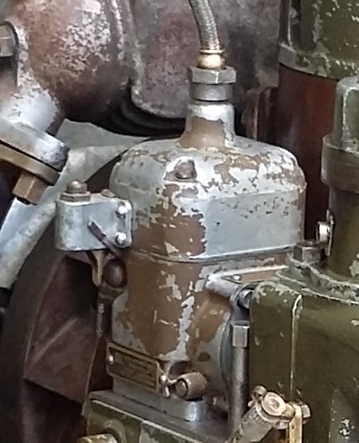
Switch positioned on the screened magneto top. The operating lever is at the bottom, adjacent to the kill button. The Bowden cable attaches to the threaded insert at the top.
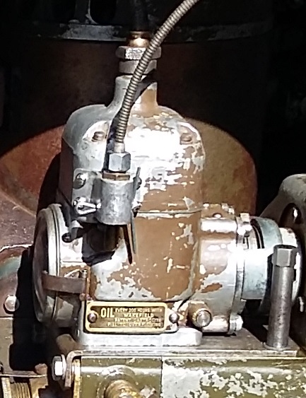
Remote switch with Bowden cable attached at the magneto end.
Mixture Control.
The Mixture control is used to adjust the carburettor mixture from weak to rich and is adjusted once the unit is under load, to achieve smooth operation without any hunting, as observed on the frequency meter. All the device is required to do, is to pull the air control slug up a split tube in the carburettor, a simple choke control lever could have achieved the same function.
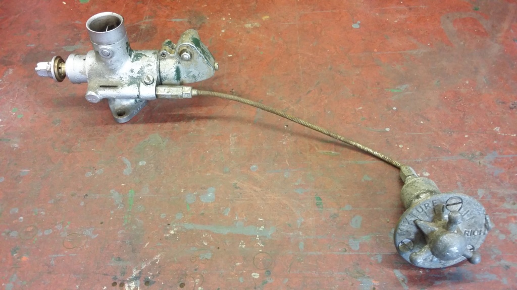
The complete arrangement removed from the set.
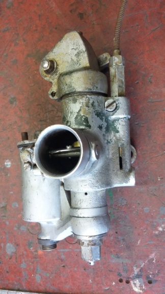
Carburettor end arrangement. The screw at the top of the tube retains the fitting, whilst allowing it to swivel, with the air control slug visible in the slot.
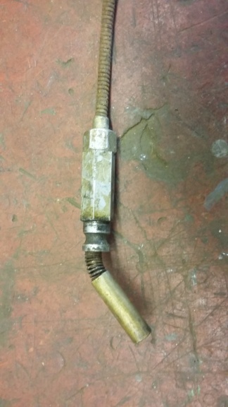
The carburettor end of the control cable, with air control slug attached. Also shows the groove in the fitting, into which the screw locates allowing rotational movement.
The control knob was removed and examined, as it was known to be seized and did not operate. On examination it was noted that the slot in the casing was damaged with metal broken away. It would seem this may have been caused by forcing the control, whilst the internal were locked solid. A repair will be needed to allow for the guide pin to slide along the edge of the slot. I believe there will be space available to mount a strip of metal onto the external edge of the slot to provide a smooth edge for the pin to slide along. What did surprise me was the total number of components involved in this simple control, far more than would have been expected or necessary with an alternative arrangement.

Control knob, showing the damage to the edge of the slot, on one side. Possibly caused by the mechanism being locked up and then being forced.
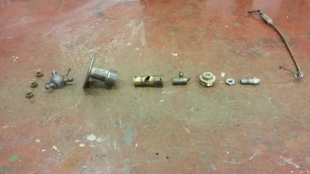
Control knob fully disassembled. This identifies the number of separate components this design requires, to achieve a simple pull function. All very impressive.
Repairing this device will keep me occupied for a while, I will also be checking over the carburettor and preparing both of these items, ready for the rebuild.
That's all for now, more to follow, if you're interested....
Neil.
The controls actually perform fairly simple tasks. The Ignition control is no more than a remote device to mechanically operate the the magneto cut out, to stop the engine. Due to the radio screening of the set, it was necessary to retain the actual switch on the magneto itself, rather than extend the wiring to a remote switch on the canopy. The control utilises a Bowden cable to push the magneto cut out button via a pivoted lever, mounted onto the metal screened top of the magneto. Due to the push action, rather than pull, the operation tends to be a little erratic. Possibly designed this way to make it more fail safe, ensuring a positive firm action was required to kill the engine.

Switch positioned on the screened magneto top. The operating lever is at the bottom, adjacent to the kill button. The Bowden cable attaches to the threaded insert at the top.

Remote switch with Bowden cable attached at the magneto end.
Mixture Control.
The Mixture control is used to adjust the carburettor mixture from weak to rich and is adjusted once the unit is under load, to achieve smooth operation without any hunting, as observed on the frequency meter. All the device is required to do, is to pull the air control slug up a split tube in the carburettor, a simple choke control lever could have achieved the same function.

The complete arrangement removed from the set.

Carburettor end arrangement. The screw at the top of the tube retains the fitting, whilst allowing it to swivel, with the air control slug visible in the slot.

The carburettor end of the control cable, with air control slug attached. Also shows the groove in the fitting, into which the screw locates allowing rotational movement.
The control knob was removed and examined, as it was known to be seized and did not operate. On examination it was noted that the slot in the casing was damaged with metal broken away. It would seem this may have been caused by forcing the control, whilst the internal were locked solid. A repair will be needed to allow for the guide pin to slide along the edge of the slot. I believe there will be space available to mount a strip of metal onto the external edge of the slot to provide a smooth edge for the pin to slide along. What did surprise me was the total number of components involved in this simple control, far more than would have been expected or necessary with an alternative arrangement.

Control knob, showing the damage to the edge of the slot, on one side. Possibly caused by the mechanism being locked up and then being forced.

Control knob fully disassembled. This identifies the number of separate components this design requires, to achieve a simple pull function. All very impressive.
Repairing this device will keep me occupied for a while, I will also be checking over the carburettor and preparing both of these items, ready for the rebuild.
That's all for now, more to follow, if you're interested....
Neil.
neil (LE)- A credit to the forum

- Posts : 399
Join date : 2012-03-21
Age : 68
Location : N/W Kent
 Re: Scott Generating Set Restoration (Continues)
Very interested Neil - keep it coming.
_________________
Regards Paul
Tha can alus tell a Yorkshireman - but tha can't tell him much.

Woodsman- Admin
- Posts : 2815
Join date : 2014-08-24
Age : 73
Location : God's own county
 Re: Scott Generating Set Restoration (Continues)
Could you build up the damaged area with something like JB weld then file it back to suit?
_________________
Stuart
Robotstar5- Life Member

- Posts : 1109
Join date : 2018-09-25
 Re: Scott Generating Set Restoration (Continues)
Hi Stuart, I don't know how successful JB Weld might be, especially as the material is some form of aluminium alloy casting. However since the last posting I've had the opportunity to clean up the control mechanism and have been able to consider the options. My original thought was to attach a strip of metal along the side of the slot for the guide pin to ride against. This idea was based around the fact that the tube wall is quite thick and it is of a reduced O.D. as compared with the threaded end boss. This would allow for a thread to be cut in the tube wall, as well as allowing room for the heads of cheese head 4 BA screws to be accommodated, without fouling the canopy mounting hole. On assembly of the freed up and cleaned components, it became apparent that although the slot edge had been damaged by the forced turning of the spindle, it wasn't actually impairing the control action. My decision now is do I proceed with the repair, using the strip of metal screwed to the slot side. Or do I leave it as it is and ensure I keep the device properly lubricated to reduce the risk of the damage becoming worse, to the point where it does affect the operation. At present I minded to leave well alone, if it becomes a problem in the future it is an easy item to get access to, to implement the repair at a later date.
During the clean up of the components, I took a closer look at the inner brass sleeve which fits inside the main housing and is used to pull the cable ferule, to operate the carburettor air slide. The main tube has a spiral cut in it, which the pin on the ferule locates into and is guided along to provide the pull action. Nothing special there but what caught my attention was the end of the tube. This is a larger diameter which means the overall diameter of the tube must have been turned down to the reduced dimension, creating a comparatively large amount of waste material for a small component. The end flange has then been undercut by hand, to about two thirds of the way through and the top edge of the flange has been slotted. My assumption of this complication was to provide a friction control for the air slide operation. This would have been to ensure it didn't move through vibration and alter the setting of the slide whilst the set was in operation. I believe this friction control is achieved by the external circumference of the flange pressing on inside of the housing and, or, the top face of the flange being gently clamped by the end fitting. Both of these actions can be adjusted by tweaking either the split gap to expand the circumference therefore the interference fit or by bending the top flange upwards to increase the pressure on the end cap. All this is supposition by me but I cannot think of any other reason for this complication on what could have been a simple flanged tube.

Close up view of the damaged slot in the main casting.

End view of casting showing the inner thickness of the tube wall which should be enough to be accept a thread.
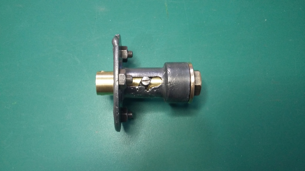
Guide pin approaching the damaged area, moving from left to right pressing on the damaged edge.
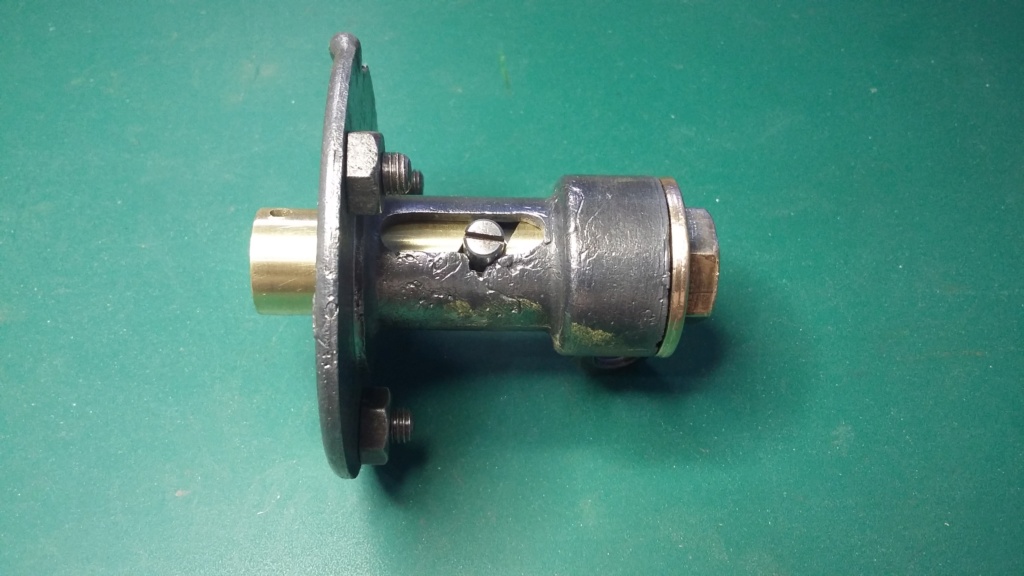
Pin encountering the worst of the damage area. It doesn't drop into it, instead it rides over it.

And out the other side.
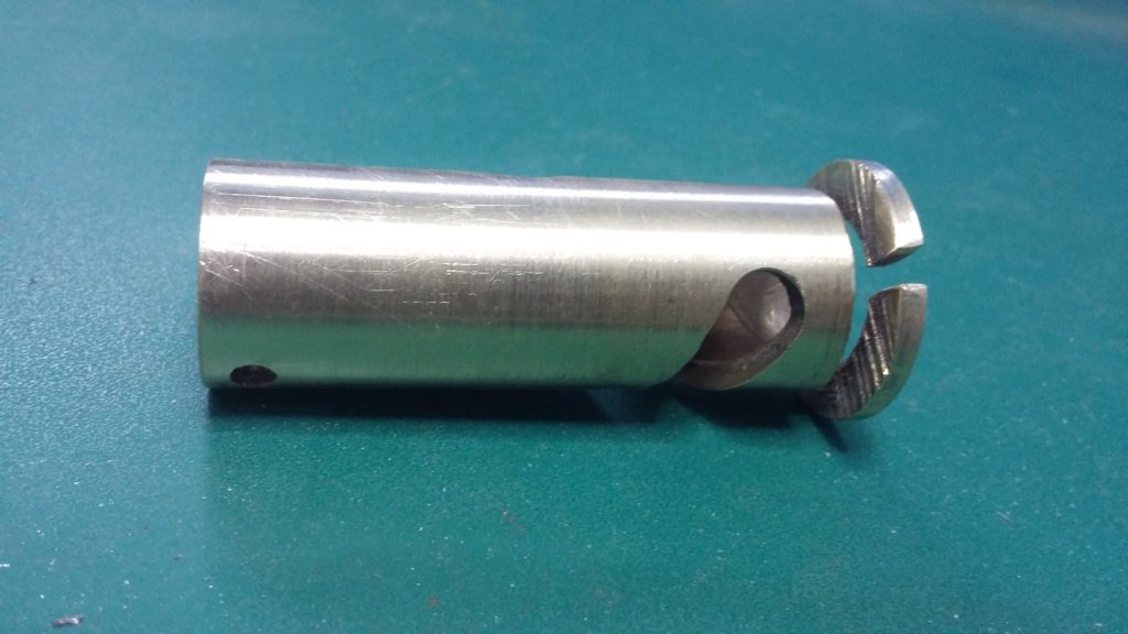
Internal brass slider with spiral slot. Note the hand cut saw marks, on the undercut top flange and the slit cut into the flange edge.
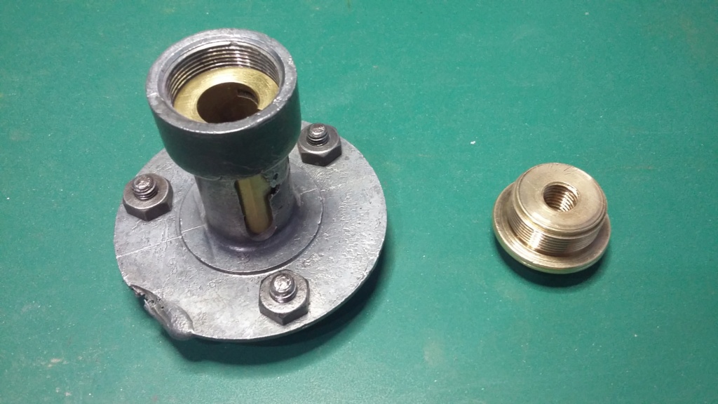
The brass insert inside the main housing, with the split flange onto which the threaded boss is screwed down onto providing the friction control, possibly?
During the clean up of the components, I took a closer look at the inner brass sleeve which fits inside the main housing and is used to pull the cable ferule, to operate the carburettor air slide. The main tube has a spiral cut in it, which the pin on the ferule locates into and is guided along to provide the pull action. Nothing special there but what caught my attention was the end of the tube. This is a larger diameter which means the overall diameter of the tube must have been turned down to the reduced dimension, creating a comparatively large amount of waste material for a small component. The end flange has then been undercut by hand, to about two thirds of the way through and the top edge of the flange has been slotted. My assumption of this complication was to provide a friction control for the air slide operation. This would have been to ensure it didn't move through vibration and alter the setting of the slide whilst the set was in operation. I believe this friction control is achieved by the external circumference of the flange pressing on inside of the housing and, or, the top face of the flange being gently clamped by the end fitting. Both of these actions can be adjusted by tweaking either the split gap to expand the circumference therefore the interference fit or by bending the top flange upwards to increase the pressure on the end cap. All this is supposition by me but I cannot think of any other reason for this complication on what could have been a simple flanged tube.

Close up view of the damaged slot in the main casting.

End view of casting showing the inner thickness of the tube wall which should be enough to be accept a thread.

Guide pin approaching the damaged area, moving from left to right pressing on the damaged edge.

Pin encountering the worst of the damage area. It doesn't drop into it, instead it rides over it.

And out the other side.

Internal brass slider with spiral slot. Note the hand cut saw marks, on the undercut top flange and the slit cut into the flange edge.

The brass insert inside the main housing, with the split flange onto which the threaded boss is screwed down onto providing the friction control, possibly?
neil (LE)- A credit to the forum

- Posts : 399
Join date : 2012-03-21
Age : 68
Location : N/W Kent
 Re: Scott Generating Set Restoration (Continues)
Seems the damage is more visual?
If it's planned to paint it I would be inclined to fill it with JB Weld first (or even if it's not painted)
Alan
If it's planned to paint it I would be inclined to fill it with JB Weld first (or even if it's not painted)
Alan
Alanengine- A credit to the forum

- Posts : 461
Join date : 2020-11-21
 Re: Scott Generating Set Restoration (Continues)
Alan, yes it looked worse than it actually was, it does seem to be operating quite well, even with the damage. As I'm not certain how JB Weld will work with aluminium casting, I'm thinking I will leave it alone, unless it proves not to work when it is connected to the carburettor.
Thanks Neil.
Thanks Neil.
neil (LE)- A credit to the forum

- Posts : 399
Join date : 2012-03-21
Age : 68
Location : N/W Kent
 Re: Scott Generating Set Restoration (Continues)
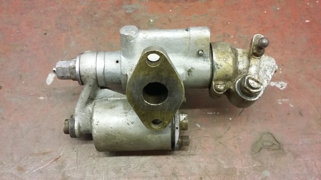
Carburettor Amal 15TT39LS
Continuing on the carburettor theme, I took the opportunity to take a closer look at the one on the set, to assess what was needed as part of the renovation process. It was obvious it had been overpainted in silver at some point in its past, although there were still traces of drab green visible underneath. Following the examination, as a repaint into drab green would be required, a full disassembly, down to its component parts was necessary. Fortunately this didn't identify any serious damage or issues. The carburettor will be cleaned up and rebuilt, as and when time is available, until then all the parts have been boxed and stored. I imagine this will end up being an infill task to be undertaken during the quieter periods of the restoration.
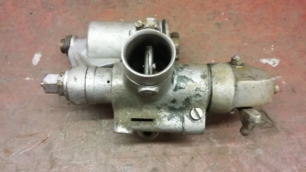
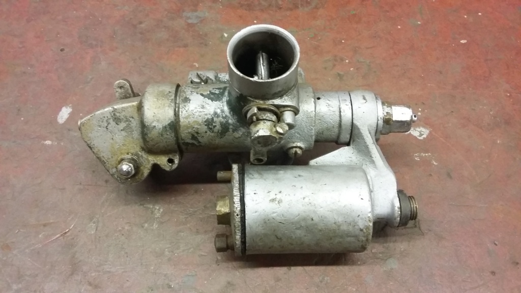
Carburettor as removed from the engine. Showing the state of the paint and the remnants of the original green.

Carburettor top showing the operating lever, slide and needle.
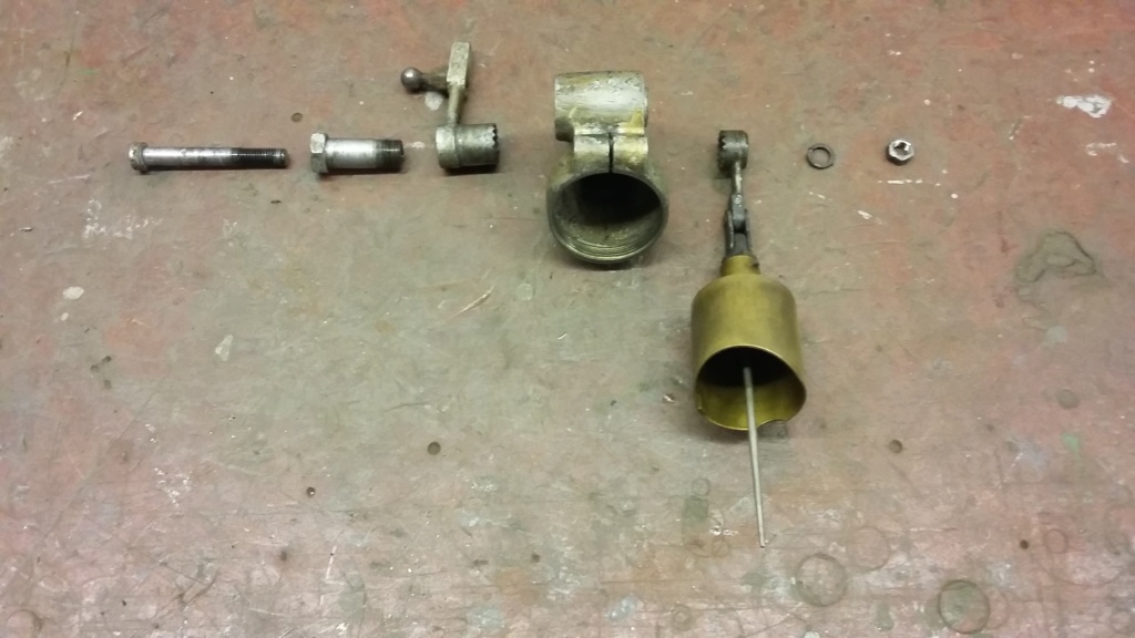
The components parts of the throttle assembly, laid out for checking. Note the serrated joint, to allow for adjustment of the operating position.
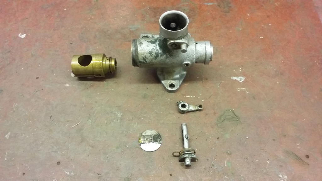
Main body internals removed.
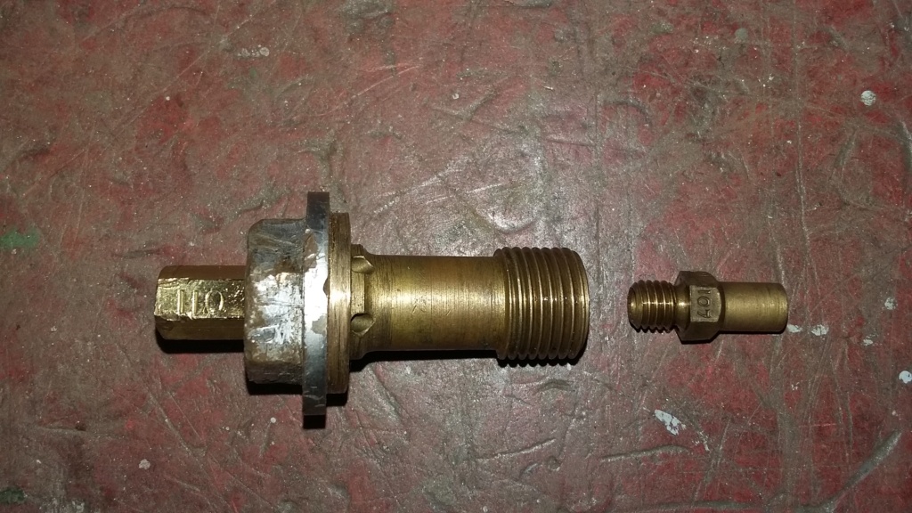
Jet block.

Dirt and muck in the float bowl, needs a good clean out.
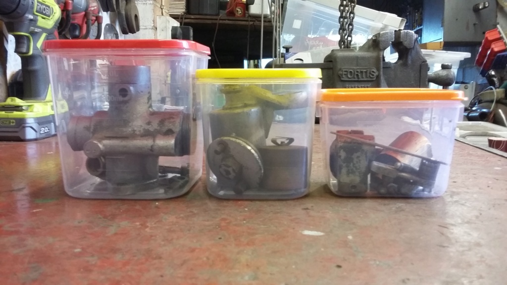
All packed away, just awaiting a rainy day. Plenty of those, these days.
Continuing on the carburettor theme, I took the opportunity to take a closer look at the one on the set, to assess what was needed as part of the renovation process. It was obvious it had been overpainted in silver at some point in its past, although there were still traces of drab green visible underneath. Following the examination, as a repaint into drab green would be required, a full disassembly, down to its component parts was necessary. Fortunately this didn't identify any serious damage or issues. The carburettor will be cleaned up and rebuilt, as and when time is available, until then all the parts have been boxed and stored. I imagine this will end up being an infill task to be undertaken during the quieter periods of the restoration.


Carburettor as removed from the engine. Showing the state of the paint and the remnants of the original green.

Carburettor top showing the operating lever, slide and needle.

The components parts of the throttle assembly, laid out for checking. Note the serrated joint, to allow for adjustment of the operating position.

Main body internals removed.

Jet block.

Dirt and muck in the float bowl, needs a good clean out.

All packed away, just awaiting a rainy day. Plenty of those, these days.
neil (LE)- A credit to the forum

- Posts : 399
Join date : 2012-03-21
Age : 68
Location : N/W Kent
 Re: Scott Generating Set Restoration (Continues)
This thread has made a good read. Thank You.
Keep up the good work.
Andrew
Keep up the good work.
Andrew
Andrew1971- A credit to the forum

- Posts : 243
Join date : 2013-01-30
Age : 53
Location : Northallerton. North Yorkshire
 Re: Scott Generating Set Restoration (Continues)
Thanks Andrew, glad you are enjoying it. Hopefully I will keep posting, as long as I have something to share with everybody. I should be able to, especially during this lockdown period, as I'm encouraged to get out in the garage by the wife. I don't know if she is trying to tell me something but it works for me, especially as the garage has the largest radiator in the house system and a hot air curtain over the bench. Toasty!
Neil.
Neil.
neil (LE)- A credit to the forum

- Posts : 399
Join date : 2012-03-21
Age : 68
Location : N/W Kent
 Re: Scott Generating Set Restoration (Continues)
A heated garage !!! All I got is a nice cold shed that needs a rebuild. 
Andrew
Andrew
Andrew1971- A credit to the forum

- Posts : 243
Join date : 2013-01-30
Age : 53
Location : Northallerton. North Yorkshire
 Re: Scott Generating Set Restoration (Continues)
As there was a recent discussion with regard to the starting handle plate, I thought it would be appropriate to include a post on the starting mechanism operation and its removal and preparation for painting.
The engine is fitted with an impulse magneto, so in theory should only require a single turn of the engine to achieve a successful start. In practise this is rarely the case and frequent attempts are normally necessary, although only a single turn of the engine at a time, is all that can be achieved. The starting handle does not directly engage with the engine but is coupled via a chain from the top canopy. The starting handle is inserted into the hollow tube and engages with the pin in the cog, then the starting instructions are followed. These state "Engage the starting dog by pushing in the lower shaft with the toe, at the same time pulling up on the starter handle". Basically you are instructed to use your foot to engage the starter pinion, which must make this one of the only engines which actually require you to “put the boot in” to engage the starting mechanism, as opposed to kick start engines, such as the MarVil, which are directly operated by foot. In fact it gets even more complicated, as at the same time you're pressing with your foot and pulling the starter handle, you are also required to pull up and hold in the operating position, the sprung loaded choke control. There is certainly a knack to starting one of these generator sets and when you consider these were required to come on line very quickly, to engage with the enemy, I wonder if a better system could have been devised.
Possibly not the most exciting aspect of an engine to consider but it can sometimes be just as interesting to wonder about the design philosophy of some of the ancillary aspects of an engine, in preference to some the more usual mainstream items. In fact a generating set of this detail, can only as good as the sum of its parts.
More to follow…
Neil.

Starting instructions, indicating the use of the toe, aka the boot, to engage the starter dog.
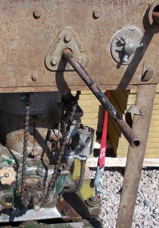
Starter handle inserted into the hollow tube in the canopy, to engage with the starter cog drive pin.

Instruction plate, indicating the need to slacken bracket prior to adjusting chain tension.
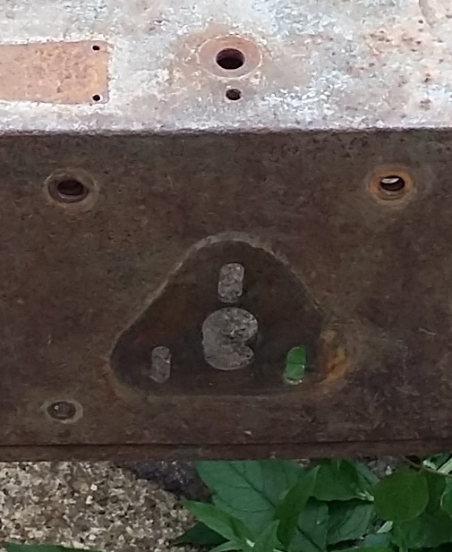
Slotted holes in canopy, to allow for chain adjustment.
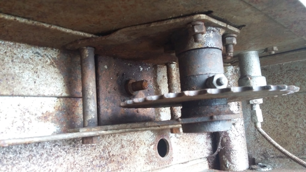
Underside of canopy showing the large starter cog for the chain. The two long and two short bolts are those marked "A" which are slackened for adjustment. The large bolt in the top plate, is used to adjust the chain tension, before re-tightening the "A" bolts.
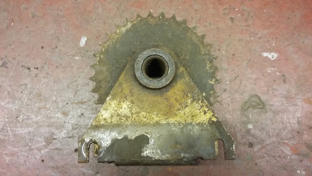
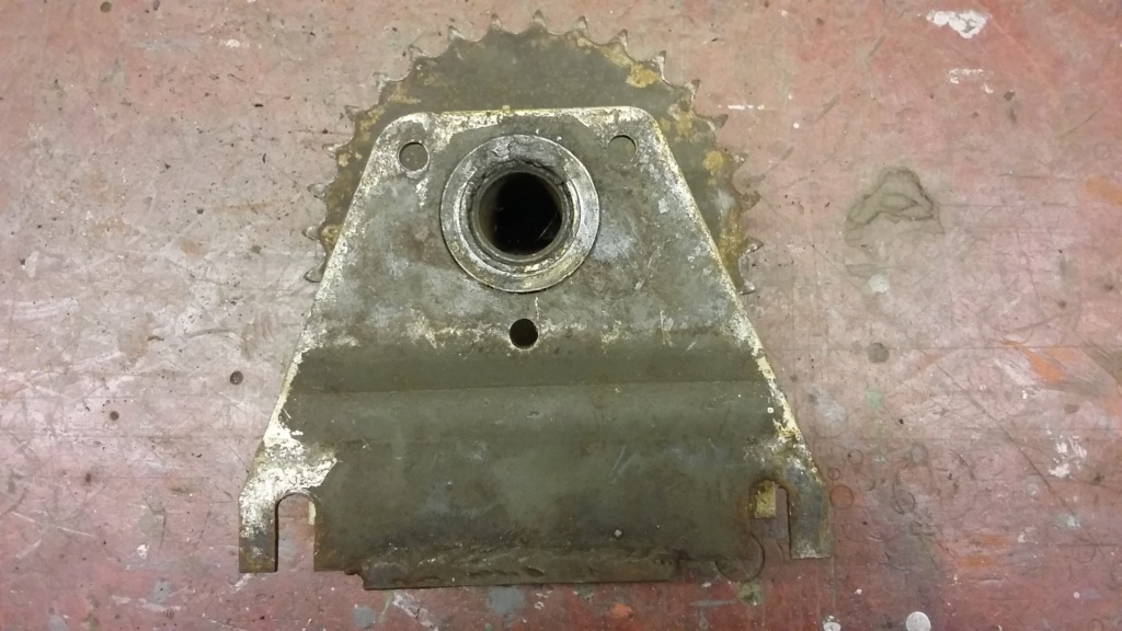
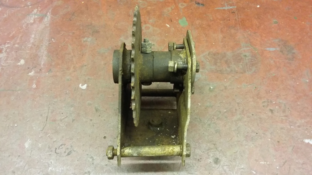
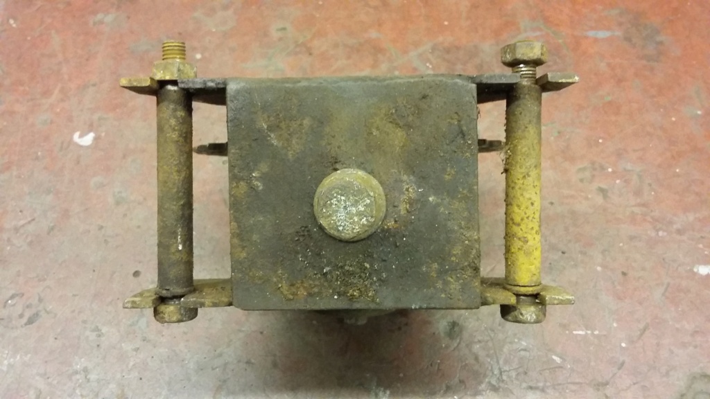
Starter gear as removed from canopy.

Then cleaned up and laid out for inspection, just like the military personnel who operated the sets.
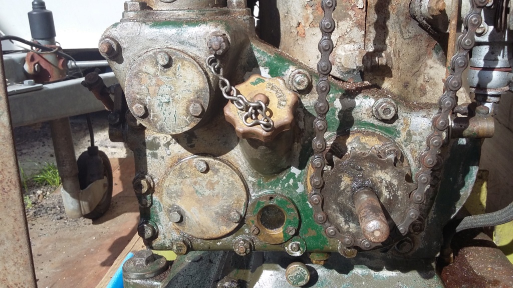
Starting chain engaged with the lower engine cog, mounted onto the sprung loaded starter dog shaft. This is engaged by the use of the operator's foot!
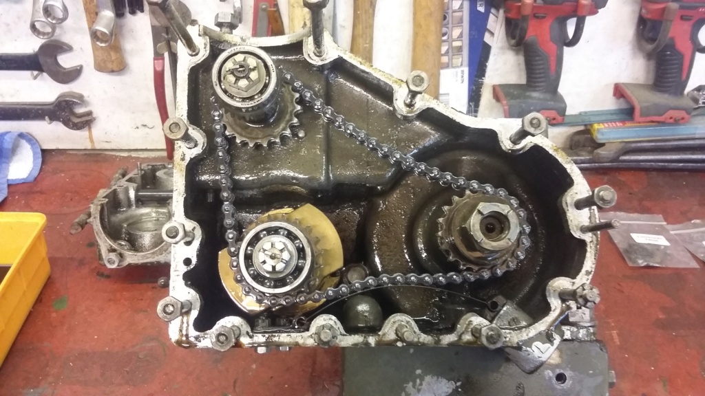
Starter dog inside the auxiliary drive case.
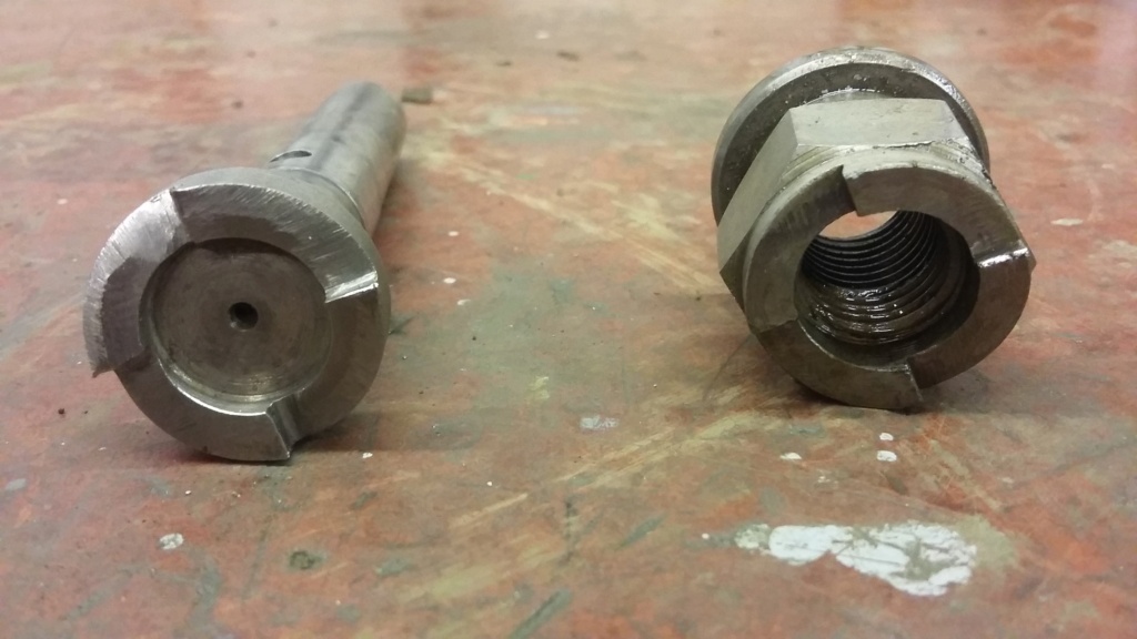
The pinion and dog, which is mounted on the end of the engine crankshaft.

Dog and pinion showing the ratchet teeth.
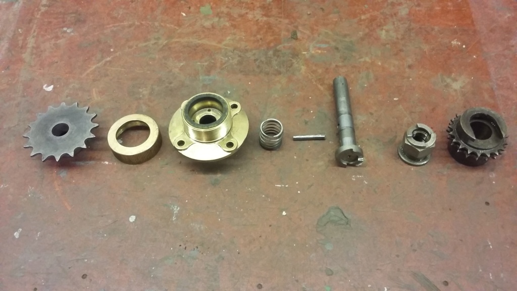
Starter mechanism laid out.
The engine is fitted with an impulse magneto, so in theory should only require a single turn of the engine to achieve a successful start. In practise this is rarely the case and frequent attempts are normally necessary, although only a single turn of the engine at a time, is all that can be achieved. The starting handle does not directly engage with the engine but is coupled via a chain from the top canopy. The starting handle is inserted into the hollow tube and engages with the pin in the cog, then the starting instructions are followed. These state "Engage the starting dog by pushing in the lower shaft with the toe, at the same time pulling up on the starter handle". Basically you are instructed to use your foot to engage the starter pinion, which must make this one of the only engines which actually require you to “put the boot in” to engage the starting mechanism, as opposed to kick start engines, such as the MarVil, which are directly operated by foot. In fact it gets even more complicated, as at the same time you're pressing with your foot and pulling the starter handle, you are also required to pull up and hold in the operating position, the sprung loaded choke control. There is certainly a knack to starting one of these generator sets and when you consider these were required to come on line very quickly, to engage with the enemy, I wonder if a better system could have been devised.
Possibly not the most exciting aspect of an engine to consider but it can sometimes be just as interesting to wonder about the design philosophy of some of the ancillary aspects of an engine, in preference to some the more usual mainstream items. In fact a generating set of this detail, can only as good as the sum of its parts.
More to follow…
Neil.

Starting instructions, indicating the use of the toe, aka the boot, to engage the starter dog.

Starter handle inserted into the hollow tube in the canopy, to engage with the starter cog drive pin.

Instruction plate, indicating the need to slacken bracket prior to adjusting chain tension.

Slotted holes in canopy, to allow for chain adjustment.

Underside of canopy showing the large starter cog for the chain. The two long and two short bolts are those marked "A" which are slackened for adjustment. The large bolt in the top plate, is used to adjust the chain tension, before re-tightening the "A" bolts.


Starter gear as removed from canopy.

Then cleaned up and laid out for inspection, just like the military personnel who operated the sets.

Starting chain engaged with the lower engine cog, mounted onto the sprung loaded starter dog shaft. This is engaged by the use of the operator's foot!

Starter dog inside the auxiliary drive case.

The pinion and dog, which is mounted on the end of the engine crankshaft.

Dog and pinion showing the ratchet teeth.

Starter mechanism laid out.
neil (LE)- A credit to the forum

- Posts : 399
Join date : 2012-03-21
Age : 68
Location : N/W Kent
 Re: Scott Generating Set Restoration (Continues)
Alternator type M.W. Woods Model No. 2Z1A
Having finished with the exciter generator for the time being, whilst I wait for better painting weather, I turned my attention to the alternator itself. This is a M.W. Woods model No. 2Z1A, which is a non, self-exciting 130 volt, 3 phase 50 Hz unit. This produces 2.75 KVA with a power factor of 0.65, providing 12.2 Amps per phase, at full load.
This is a rather large and heavy unit and needed to be carefully lifted onto the bench for attention, to ensure that no damage was caused to either the alternator, or more importantly to myself. The total weight is about 50 Kgs (8 St / 112 lbs), without the exciter generator. Initial assessment indicated that although it was externally in need of a good clean and repaint, there was no obvious damage or immediate cause for concern. I was however worried what I might find internally, so I focused on how to disassemble the unit, to allow an internal inspection to take place.
Either end of the armature shaft extends beyond the body of the housing and is used to drive the exciter pulley at one end and the on the other end is mounted the fan blade and the drive spider, which engages to the engine flexible coupler. These three items are fitted on the armature parallel shaft with a key to retain them, so would need to be pulled off, to allow access to the alternator internals. I started with the exciter pulley, as it seemed to be the easiest option. Following the removal of the split pin and a clean-up of the shaft, a three legged puller was utilised to remove the pulley. This was aided by the use of some gentle heat, being respectful of the fact that the pulley is cast aluminium alloy and windings are attached to the shaft. This soon resulted in the pulley being removed without any noticeable damage being caused.
Attention then turned to the other end of the armature shaft, which has the other two separate items to be pulled off, the coupling spider and the fan unit. Unfortunately neither part would allow a puller to be easily utilised, as the two components were pressed hard together without an accessible space for the puller legs to engage. Initial attempt to pull the two items as one, using the fan blades wasn’t going to work and would risk breaking the cast aluminium alloy fan in the process.
The spider needed to be extracted first but due to its shape the puller would only attach to the very ends of the spider legs. When this was attempted it was obvious that the spider legs would bend before it could be pulled off the shaft. In the end I used a selection of drill bit shafts and studding, wedged behind the drive pin nuts as packing, to pull against. Initially, with the application of heat, this resulted in a minor success, with a small gap appearing but no more. I left it overnight and attempted again the following day. This time instead of using drill bits, I decided square section material would provide a better purchase. I didn’t have anything suitable to hand, so looking around, I found a broken garden fork that the wife used as a hand tool. I decided to sacrifice the fork and ground off the tines to produce the square section packing required. With these in place and the judicious use of heat, the spider was carefully withdrawn.
Once this had been successfully achieved the fan followed. This produced a different challenge, as the puller would only attach to the front edge of the fan blade, with one leg having to be central to the webs, therefore the weakest point. This time the tines were cut to fit between the fan webs to spread the pulling load, which with more heat, produced a successful outcome, for the second time.
This should now allow the casing to be separated, for the first look inside and hopefully for the armature and the bearings to be removed….?
Neil
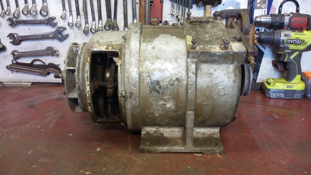
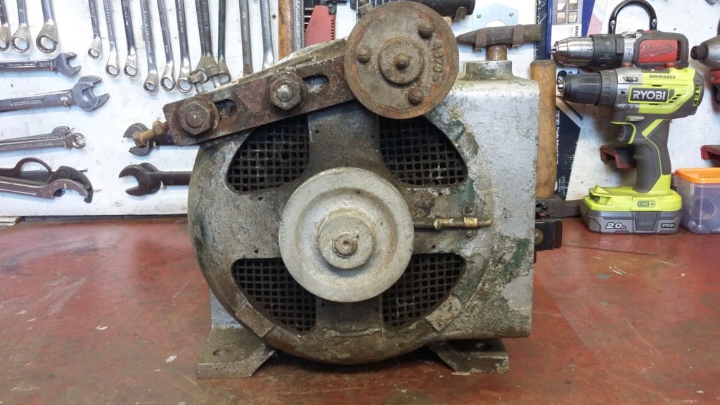
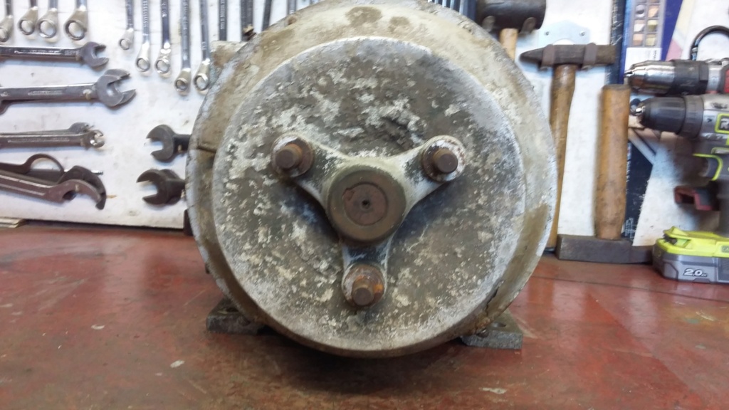
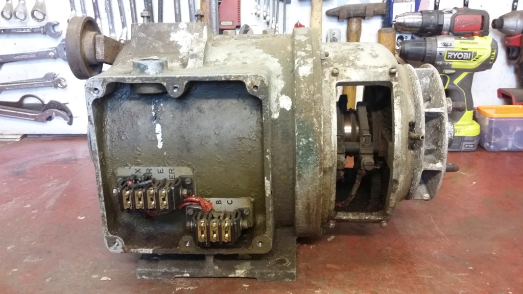
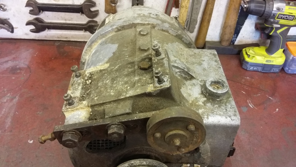
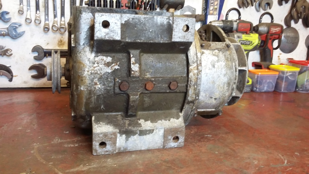
Up on the bench for the first time, for a quick overview of the state of the alternator, with no obvious visual issues.
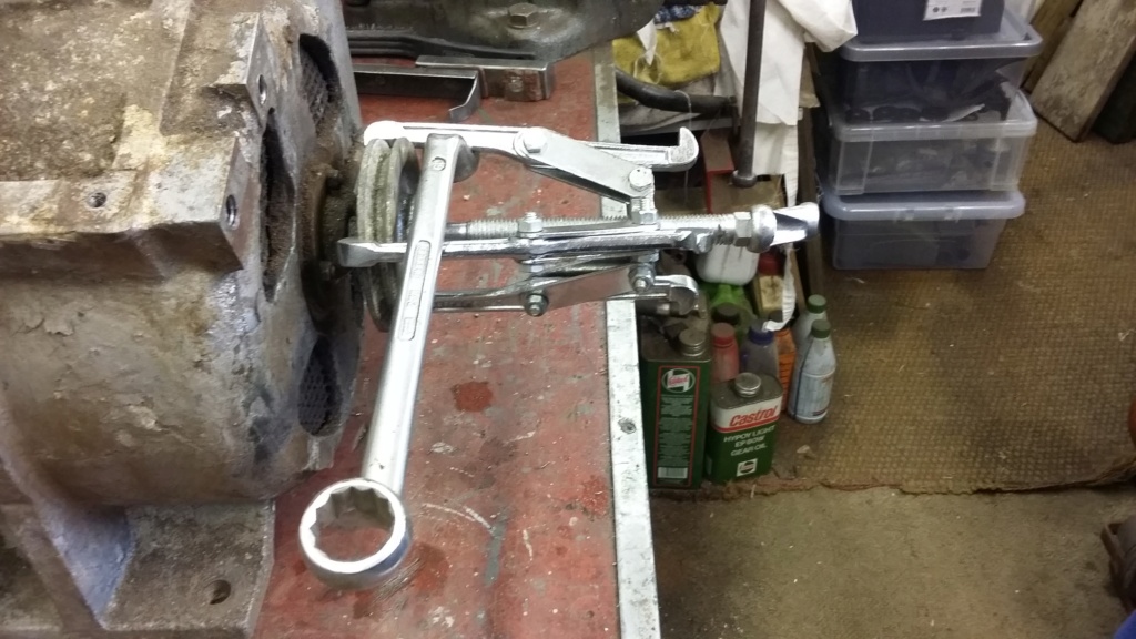
Exciter pulley being drawn off the armature shaft.
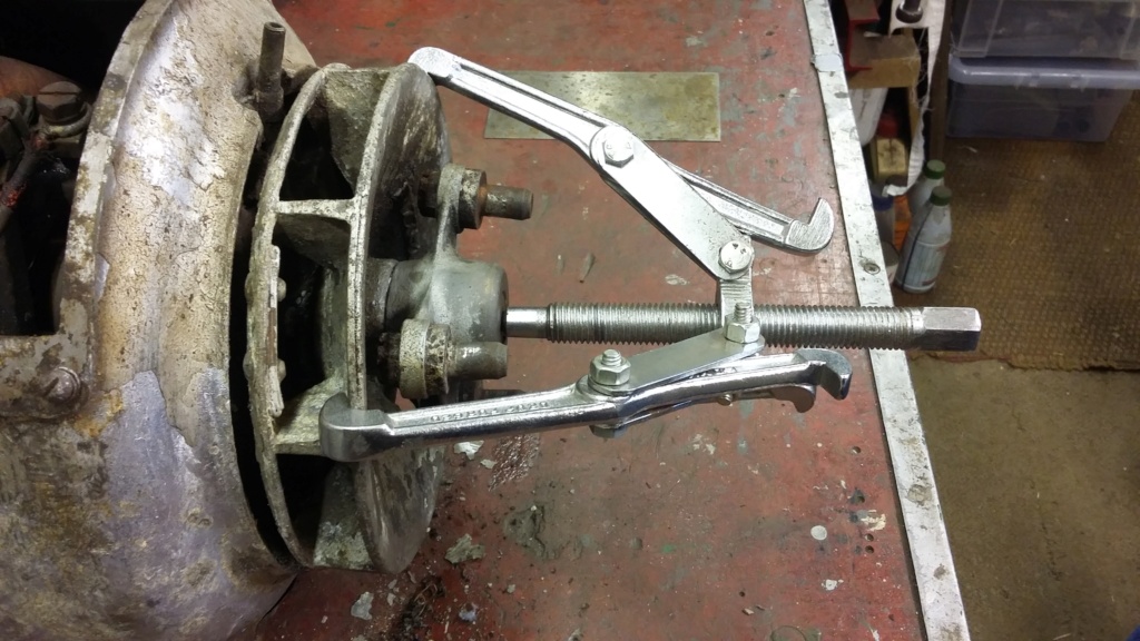
Initial but ultimately unsuccessful attempt two remove both the fan blade and the coupler together.
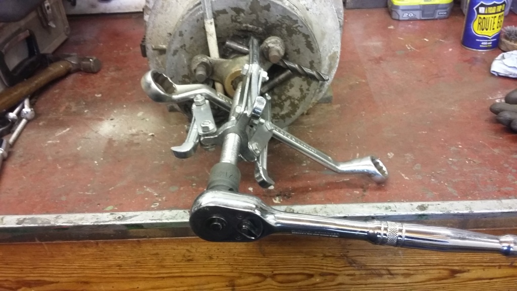
First attempt to remove coupler, utilising drill bits and studding. Only partially successful.
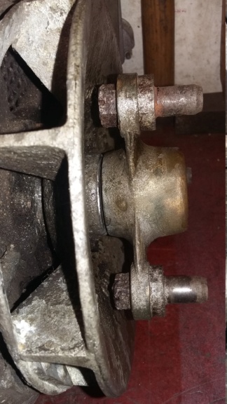
Small gap achieved but going no further.

Success! Note the fork tine on the bench which was used instead of the drill bits to provide better purchase.
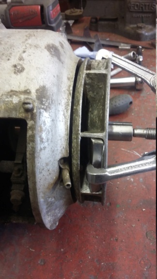
Fork tine used in fan blade to spread the load, to aid puller action.
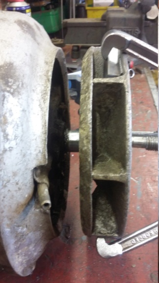
Successfully pulling the fan blade off the shaft, without any damage.

Shaft and key finally exposed.
Having finished with the exciter generator for the time being, whilst I wait for better painting weather, I turned my attention to the alternator itself. This is a M.W. Woods model No. 2Z1A, which is a non, self-exciting 130 volt, 3 phase 50 Hz unit. This produces 2.75 KVA with a power factor of 0.65, providing 12.2 Amps per phase, at full load.
This is a rather large and heavy unit and needed to be carefully lifted onto the bench for attention, to ensure that no damage was caused to either the alternator, or more importantly to myself. The total weight is about 50 Kgs (8 St / 112 lbs), without the exciter generator. Initial assessment indicated that although it was externally in need of a good clean and repaint, there was no obvious damage or immediate cause for concern. I was however worried what I might find internally, so I focused on how to disassemble the unit, to allow an internal inspection to take place.
Either end of the armature shaft extends beyond the body of the housing and is used to drive the exciter pulley at one end and the on the other end is mounted the fan blade and the drive spider, which engages to the engine flexible coupler. These three items are fitted on the armature parallel shaft with a key to retain them, so would need to be pulled off, to allow access to the alternator internals. I started with the exciter pulley, as it seemed to be the easiest option. Following the removal of the split pin and a clean-up of the shaft, a three legged puller was utilised to remove the pulley. This was aided by the use of some gentle heat, being respectful of the fact that the pulley is cast aluminium alloy and windings are attached to the shaft. This soon resulted in the pulley being removed without any noticeable damage being caused.
Attention then turned to the other end of the armature shaft, which has the other two separate items to be pulled off, the coupling spider and the fan unit. Unfortunately neither part would allow a puller to be easily utilised, as the two components were pressed hard together without an accessible space for the puller legs to engage. Initial attempt to pull the two items as one, using the fan blades wasn’t going to work and would risk breaking the cast aluminium alloy fan in the process.
The spider needed to be extracted first but due to its shape the puller would only attach to the very ends of the spider legs. When this was attempted it was obvious that the spider legs would bend before it could be pulled off the shaft. In the end I used a selection of drill bit shafts and studding, wedged behind the drive pin nuts as packing, to pull against. Initially, with the application of heat, this resulted in a minor success, with a small gap appearing but no more. I left it overnight and attempted again the following day. This time instead of using drill bits, I decided square section material would provide a better purchase. I didn’t have anything suitable to hand, so looking around, I found a broken garden fork that the wife used as a hand tool. I decided to sacrifice the fork and ground off the tines to produce the square section packing required. With these in place and the judicious use of heat, the spider was carefully withdrawn.
Once this had been successfully achieved the fan followed. This produced a different challenge, as the puller would only attach to the front edge of the fan blade, with one leg having to be central to the webs, therefore the weakest point. This time the tines were cut to fit between the fan webs to spread the pulling load, which with more heat, produced a successful outcome, for the second time.
This should now allow the casing to be separated, for the first look inside and hopefully for the armature and the bearings to be removed….?
Neil


Up on the bench for the first time, for a quick overview of the state of the alternator, with no obvious visual issues.

Exciter pulley being drawn off the armature shaft.

Initial but ultimately unsuccessful attempt two remove both the fan blade and the coupler together.

First attempt to remove coupler, utilising drill bits and studding. Only partially successful.

Small gap achieved but going no further.

Success! Note the fork tine on the bench which was used instead of the drill bits to provide better purchase.

Fork tine used in fan blade to spread the load, to aid puller action.

Successfully pulling the fan blade off the shaft, without any damage.

Shaft and key finally exposed.
neil (LE)- A credit to the forum

- Posts : 399
Join date : 2012-03-21
Age : 68
Location : N/W Kent
 Re: Scott Generating Set Restoration (Continues)
Nice work! You have to be so careful with old aluminium castings as I've found them to be very brittle.
That looks a heavy unit. The generator fitted to my Villiers was bad enough, 2kw and only one bearing, as the other end fitted direct to the crankshaft.
I would have liked to clean the windings of it but hesitated at applying any liquids eventually just used a paint brush and airline to blow it all out, well most of it!
What are your plans on internal cleaning?
Alan
Alanengine- A credit to the forum

- Posts : 461
Join date : 2020-11-21
 Re: Scott Generating Set Restoration (Continues)
Alan, I will be covering the cleaning and preparation once I have the casing opened up and armature and bearings removed. When I've had a chance to have a proper examination of the state of the alternator internals, I will consider my options. However due to the alternator's construction and the state of the wiring, I will be taking a rather risk adverse approach, to protect it all from any unnecessary damage. I imagine I will be utilising a dry process, such as air line and brushes as you have done, rather than any liquids.
Neil
Neil
neil (LE)- A credit to the forum

- Posts : 399
Join date : 2012-03-21
Age : 68
Location : N/W Kent
 Re: Scott Generating Set Restoration (Continues)
That's a good outcome. I recon a good selection of various sizes/types of pullers (I think I've got about half a dozen) are probably the most useful tools you can have when playing with old kit.
A tip I came across years ago is to put a strong elastic band around the legs of the puller, to save having to use your 'third hand' to hold it all in place as you tighten it up.
A tip I came across years ago is to put a strong elastic band around the legs of the puller, to save having to use your 'third hand' to hold it all in place as you tighten it up.
_________________
Specialist in precision guesswork.

mattblack- Life Member

- Posts : 889
Join date : 2019-06-21
Location : Leicester, me duck...
 Re: Scott Generating Set Restoration (Continues)
This is really good thread with good pictures Neil; are you going to take one, of the wife's face, when she discovers what you done to her gardening tool?
oldgit- A true Stationary engine owner

- Posts : 163
Join date : 2019-07-07
 Re: Scott Generating Set Restoration (Continues)
Thanks for the feedback, much appreciated.
Mattblack, sounds like a useful idea, I had thought about using heavy duty tie wraps and slowly zipping them up as I applied torque on the puller. In this case I didn't need to, although another pair of hands might have helped. To assist in holding everything in the right place, I did use tape on the fan wheel to hold the fork tines in place (see last two pictures). This did make it marginally easier, even though it still took a few attempts to get everything to stay in the correct position, as I tightened the puller, I'll try the rubber band idea next time.
Oldgit, unfortunately, or perhaps I should say fortunately, I didn't capture the moment. Although I have to say she wasn't too concerned, as she now knows she will have a free hand next time we visit the Garden Centre!
Hopefully another update will be posted shortly.
Neil.
neil (LE)- A credit to the forum

- Posts : 399
Join date : 2012-03-21
Age : 68
Location : N/W Kent
 Re: Scott Generating Set Restoration (Continues)
Alternator type M.W. Woods Model No. 2Z1A
The Big Reveal (The initial assessment of the internal condition)
With everything pulled off either end of the armature shaft, the process of examining the internal condition of the alternator could commence. To enable the commutator end bell cover to be removed, the wiring had to be disconnected from the brush carriers. Although the wiring was designed to carry over 12 amps and is therefore of a substantial gauge, it is now about 75 years old. This means the conductor is very likely to be brittle through work hardening and the insulation is liable to be breaking down. With this in mind, I will be very respectful of the wiring, especially as it is directly connected into the coils, making repairs very difficult. With the wires carefully disconnected and marked, the bell housing, complete with the brush carrier, could be removed. First impressions were quite good, with the brushes looking to be in reasonable condition, with what seems to be sufficient carbon length to allow the set to operate for a long time, considering my actual likely use of the set.
With the brush housing set aside for cleaning and painting, the armature was next to be examined. Again I was very happy with the appearance of the coil wiring and the slip rings, with no obvious discernible damage on either of these potentially vulnerable items. In fact initial observations would seem to indicate a relatively low level of use and hopefully no abuse. Unfortunately I won't be able to confirm the state of the alternator until the set is fully up and running, unless I'm able to determine a way to jury rig a set-up, to perform some tests.
The armature was eased out of the housing, complete with its bearings, just leaving the stator and field coils within the main casting. Due to the design of the main casting and the wiring layout, it will not be possible to strip the unit any further, without risking major damage. It was a surprise to find that the alternator casting was only a two piece unit and did not split at the pulley end. Unfortunately the wiring from the external terminal block enters the housing at the blind end of the casting and is directly connected to the stator windings. This makes it impossible to renew the wiring, without removing the windings with all the leads attached, something I'm not willing to attempt. Therefore any internal cleaning of the housing will have to be undertaken with the coils and the wiring in place. This will limit the cleaning process to the use of soft brushes and a vacuum cleaner and no liquid solvents. The only real issue with not fully cleaning the inside of the alternator would be the risk of electrical tracking, caused by carbon dust from the brushes. So the focus will be to ensure as much of the carbon dust is removed as possible, without causing any unintentional damage.
The next phase will be to clean and prepare the housing for painting....
Neil.
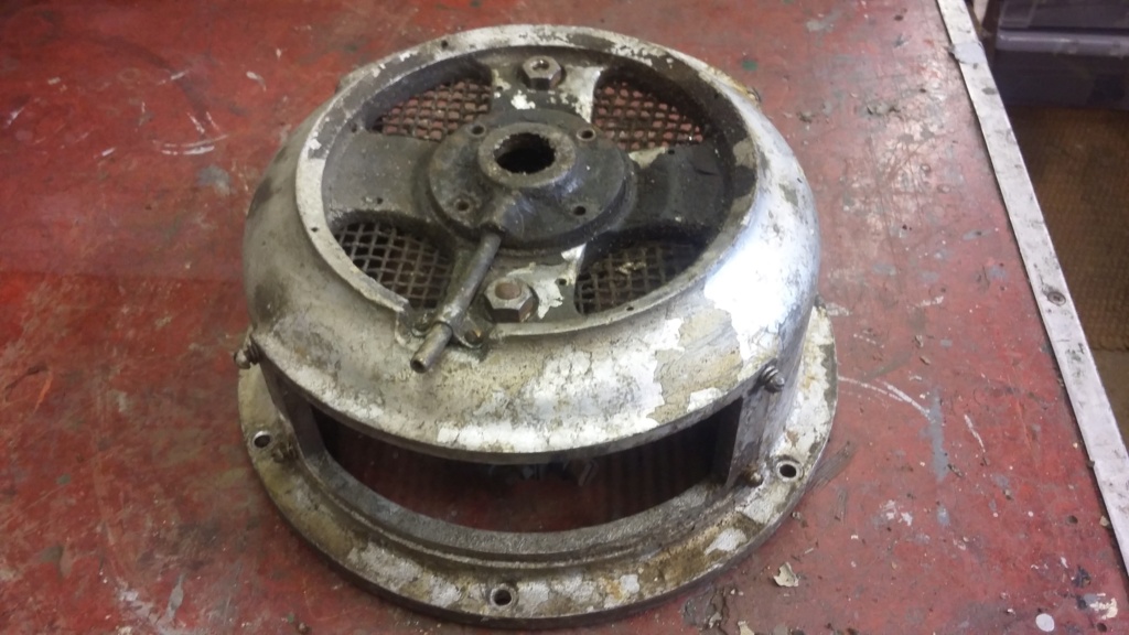
Brush bell housing removed from the main unit. Note the bearing greaser casting still attached, minus the grease cup. There are two cups missing which I need to source.
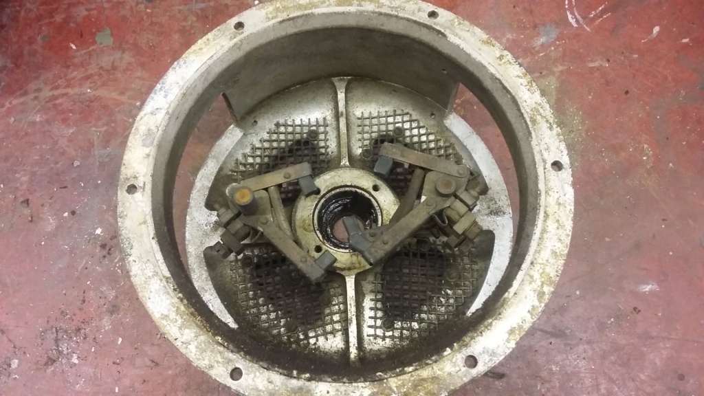
Overall internal condition of the bell housing.
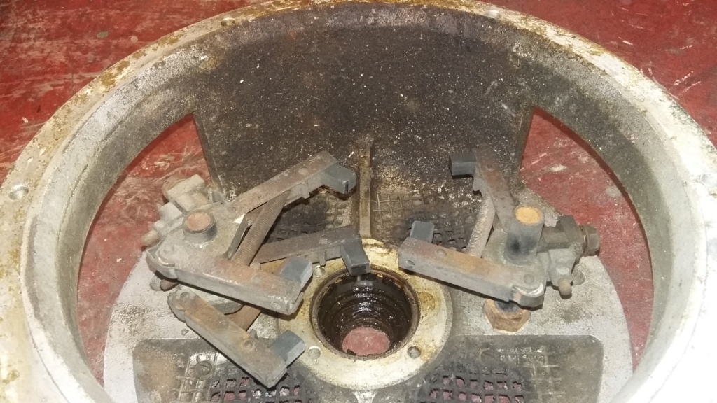
Carbon dust deposits built up inside, which will need to be cleaned out.
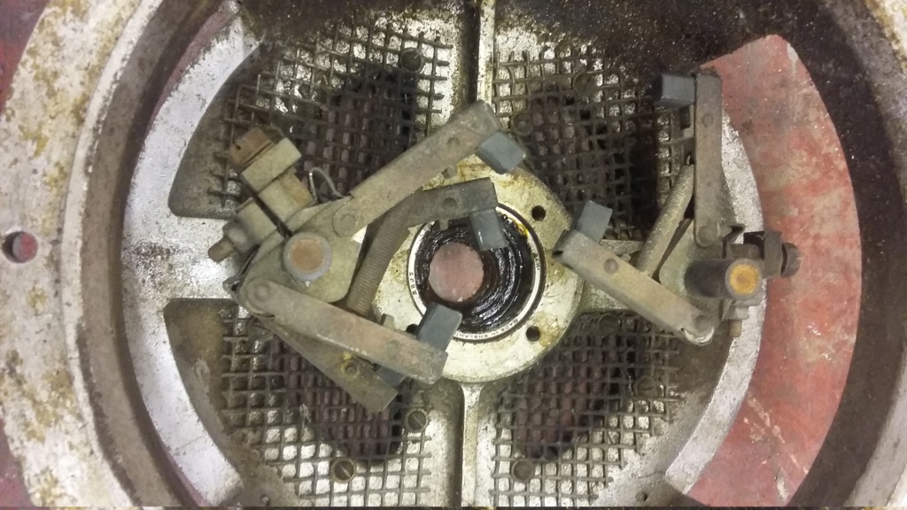
Close up view of the brush carriers and the carbon brushes. These seem to be in reasonable, to good condition.
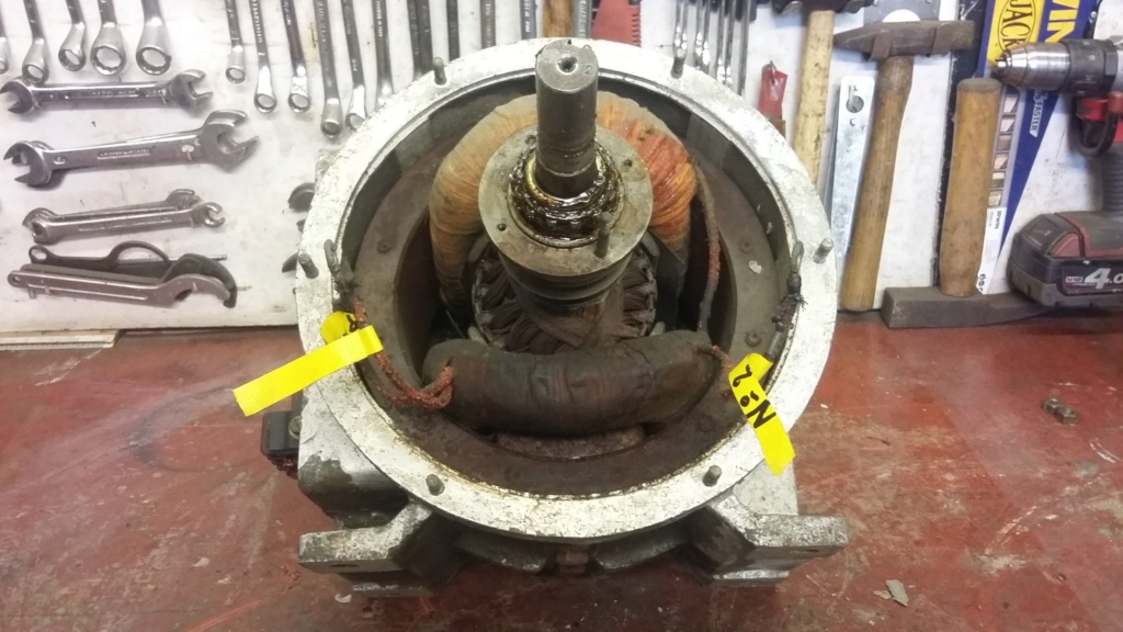
First view of the inside of the armature housing. Note that the disconnected brush wires are directly connected into the stator windings and will need to be handled with care.
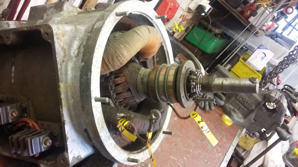
Side view showing the bearing, slip rings and armature windings still in the housing.
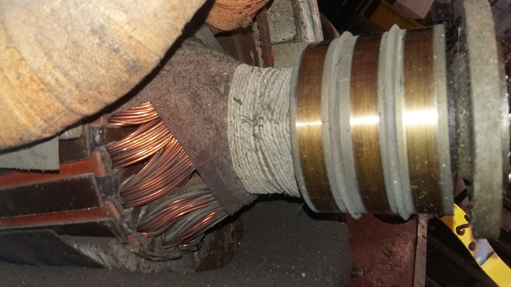
Close up of the slip rings, the windings and the bindings whilst still in the armature housing.
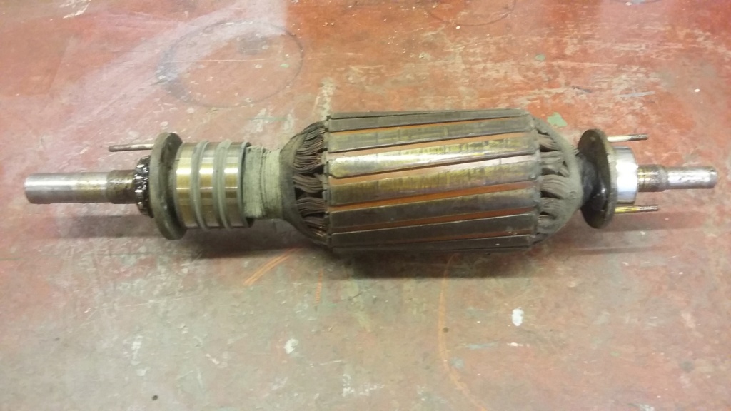
Complete armature with bearings and bearing retainers, as removed from the housing.
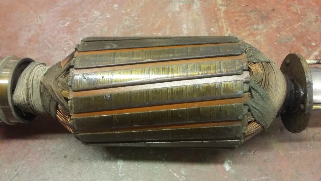
View of the armature laminates, windings and bindings. As removed before any cleaning, all looking to be in good condition.

Close up of the slip rings, should only require a gentle clean to return them to service.
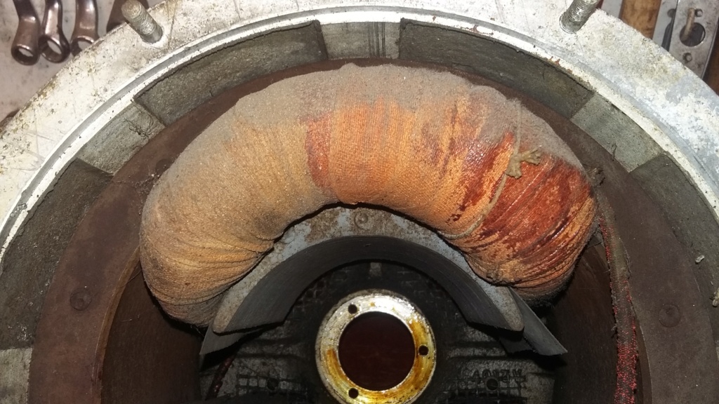
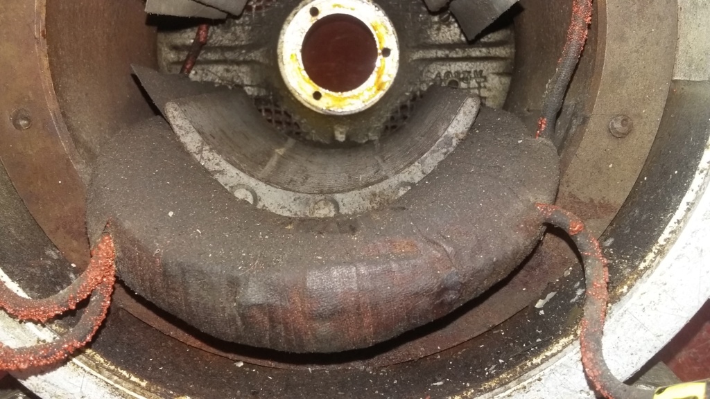
Upper and lower stator coils with the armature removed. The lower one may need some gentle cleaning, to remove carbon dust and bearing grease.
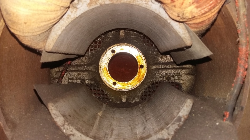
Inside view to the rear of the housing, which could prove difficult to clean due to the construction of the alternator housing.
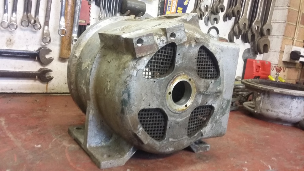
Rear view of the armature housing which is a single casting, making very difficult to clean and to access the internal wiring.
The Big Reveal (The initial assessment of the internal condition)
With everything pulled off either end of the armature shaft, the process of examining the internal condition of the alternator could commence. To enable the commutator end bell cover to be removed, the wiring had to be disconnected from the brush carriers. Although the wiring was designed to carry over 12 amps and is therefore of a substantial gauge, it is now about 75 years old. This means the conductor is very likely to be brittle through work hardening and the insulation is liable to be breaking down. With this in mind, I will be very respectful of the wiring, especially as it is directly connected into the coils, making repairs very difficult. With the wires carefully disconnected and marked, the bell housing, complete with the brush carrier, could be removed. First impressions were quite good, with the brushes looking to be in reasonable condition, with what seems to be sufficient carbon length to allow the set to operate for a long time, considering my actual likely use of the set.
With the brush housing set aside for cleaning and painting, the armature was next to be examined. Again I was very happy with the appearance of the coil wiring and the slip rings, with no obvious discernible damage on either of these potentially vulnerable items. In fact initial observations would seem to indicate a relatively low level of use and hopefully no abuse. Unfortunately I won't be able to confirm the state of the alternator until the set is fully up and running, unless I'm able to determine a way to jury rig a set-up, to perform some tests.
The armature was eased out of the housing, complete with its bearings, just leaving the stator and field coils within the main casting. Due to the design of the main casting and the wiring layout, it will not be possible to strip the unit any further, without risking major damage. It was a surprise to find that the alternator casting was only a two piece unit and did not split at the pulley end. Unfortunately the wiring from the external terminal block enters the housing at the blind end of the casting and is directly connected to the stator windings. This makes it impossible to renew the wiring, without removing the windings with all the leads attached, something I'm not willing to attempt. Therefore any internal cleaning of the housing will have to be undertaken with the coils and the wiring in place. This will limit the cleaning process to the use of soft brushes and a vacuum cleaner and no liquid solvents. The only real issue with not fully cleaning the inside of the alternator would be the risk of electrical tracking, caused by carbon dust from the brushes. So the focus will be to ensure as much of the carbon dust is removed as possible, without causing any unintentional damage.
The next phase will be to clean and prepare the housing for painting....
Neil.

Brush bell housing removed from the main unit. Note the bearing greaser casting still attached, minus the grease cup. There are two cups missing which I need to source.

Overall internal condition of the bell housing.

Carbon dust deposits built up inside, which will need to be cleaned out.

Close up view of the brush carriers and the carbon brushes. These seem to be in reasonable, to good condition.

First view of the inside of the armature housing. Note that the disconnected brush wires are directly connected into the stator windings and will need to be handled with care.

Side view showing the bearing, slip rings and armature windings still in the housing.

Close up of the slip rings, the windings and the bindings whilst still in the armature housing.

Complete armature with bearings and bearing retainers, as removed from the housing.

View of the armature laminates, windings and bindings. As removed before any cleaning, all looking to be in good condition.

Close up of the slip rings, should only require a gentle clean to return them to service.


Upper and lower stator coils with the armature removed. The lower one may need some gentle cleaning, to remove carbon dust and bearing grease.

Inside view to the rear of the housing, which could prove difficult to clean due to the construction of the alternator housing.

Rear view of the armature housing which is a single casting, making very difficult to clean and to access the internal wiring.
neil (LE)- A credit to the forum

- Posts : 399
Join date : 2012-03-21
Age : 68
Location : N/W Kent
 Re: Scott Generating Set Restoration (Continues)
Amazing how slip rings can run for years and show very little or no wear! Appears reasonably clean inside should brush and blow out quite well.
Your right about those old original cables they won't take kindly to being manhandled!
Alan
Your right about those old original cables they won't take kindly to being manhandled!
Alan
Alanengine- A credit to the forum

- Posts : 461
Join date : 2020-11-21
 Re: Scott Generating Set Restoration (Continues)
The field coils are secured with the two sets of three bolts visible on the outside of the casing. Might be worth trying to see how loose these are ?? It is also possible to use heat shrink wrap on the old cables to make them a little more robust and electrically safer.
_________________
blue cat
blue cat- Life Member

- Posts : 1065
Join date : 2013-10-10
 Re: Scott Generating Set Restoration (Continues)
Thanks for your comments, hopefully the slip rings will need no more than a wipe over with some electrical contact cleaning fluid, to restore them to "as new" condition.
Blue cat, if your comment was to recommend that I ensure the field coils bolts are fully tight, I will certainly be checking those, thank you. If however you were suggesting that I see if they can be undone, to enable the coils to be removed, then I think I will pass on that suggestion, as I really don't want to risk it. With regard to the use of heat shrink tubing, then great minds think alike. I have already looked at that possibility, however there is a limited opportunity to achieve this. It will be possible to use it on the brush to coil leads, as there is an open end to slide the sleeve over but the interconnecting wires between the coils will present difficulties. I have wondered if heat shrink can be split along its length and placed over the wire then heat shrunk, if so I will attempt this approach. The wiring at the other end in the connection block will be able to have heat shrink applied as far along the wire as I can manage, until it disappears inside the armature casing. At least it might provide some insulation protection where the wires are pressing against the edge of the metal casting, thereby reducing the risk of a short circuit.
Next update will cover the continued preparation of the alternator for painting....
Neil.
neil (LE)- A credit to the forum

- Posts : 399
Join date : 2012-03-21
Age : 68
Location : N/W Kent
 Re: Scott Generating Set Restoration (Continues)
if tou split heat shrink along its length and heat it it will still shrink but into a tight little ball, insulation tape carefully applied will be adequate.
Maryalice
Maryalice
maryalice- Life Member

- Posts : 1310
Join date : 2010-01-23
Age : 70
Location : Bedfordshire
 Re: Scott Generating Set Restoration (Continues)
I've used fibreglass tape for insulation inside motors, example - https://uk.rs-online.com/web/p/duct-tapes/8855224/
_________________
Stuart

Robotstar5- Life Member

- Posts : 1109
Join date : 2018-09-25
 Re: Scott Generating Set Restoration (Continues)
Thanks for the advice, I did wonder if the heat shrink would curl up, so that won't work. I quite like the look of the fibreglass tape, I've not come across that before. Certainly looks like it is designed for this use. I will look to see if it is available in red and/or black, as that would be preferable to white.
Neil.
Neil.
neil (LE)- A credit to the forum

- Posts : 399
Join date : 2012-03-21
Age : 68
Location : N/W Kent
Page 3 of 13 •  1, 2, 3, 4 ... 11, 12, 13
 Similar topics
» Scott PAB Restoration
» Kubota diesel KND3
» Trolley for Villiers Mk15 wooden toolbox new pics 5-9-2016
» Petter generating set - might turn into a project
» Douglas FT35 generating set
» Kubota diesel KND3
» Trolley for Villiers Mk15 wooden toolbox new pics 5-9-2016
» Petter generating set - might turn into a project
» Douglas FT35 generating set
Page 3 of 13
Permissions in this forum:
You cannot reply to topics in this forum