Scott Generating Set Restoration (Continues)
+9
Robotstar5
nickh
RichieR
oldgit
Andrew1971
maryalice
blue cat
StuartTurnerSteve
Woodsman
13 posters
Page 9 of 13
Page 9 of 13 •  1, 2, 3 ... 8, 9, 10, 11, 12, 13
 Re: Scott Generating Set Restoration (Continues)
Nice job, next time use a 1mm slitting wheel at an angle, its quick and less stressful or a large cold chisel to crack the outer and inner rings.
Maryalice
Maryalice
maryalice- Life Member

- Posts : 1310
Join date : 2010-01-23
Age : 70
Location : Bedfordshire
 Re: Scott Generating Set Restoration (Continues)
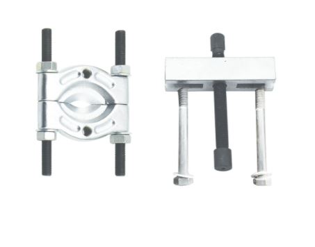
I've never thought of using a normal puller on a bearing separator, I've always used the pulling bolts with this type.
It may be worth contacting a company called Servo Connectors - https://www.servoconnectors.co.uk/ with decent photos and measurements of the socket you want to match the plug to, they have identified and supplied a few different types for me over the years.

It may be worth contacting a company called Servo Connectors - https://www.servoconnectors.co.uk/ with decent photos and measurements of the socket you want to match the plug to, they have identified and supplied a few different types for me over the years.
_________________
Stuart
Robotstar5- Life Member

- Posts : 1109
Join date : 2018-09-25
 Re: Scott Generating Set Restoration (Continues)
Hi Stuart, it initially surprised me that the bearing separator could be used with the standard puller. It was identified as suitable for use with both push pullers and jaw type pullers, by the supplying company. As the 2/3 legged puller was cheaper and potentially more useful I went for that combination. Thank you for the link to the connector suppliers, it could prove very useful.
Maryalice, If I get stuck trying to remove another bearing I will remember your method, thanks.
Neil.
Maryalice, If I get stuck trying to remove another bearing I will remember your method, thanks.
Neil.
neil (LE)- A credit to the forum

- Posts : 399
Join date : 2012-03-21
Age : 68
Location : N/W Kent
 Re: Scott Generating Set Restoration (Continues)
The engine rebuild starts…. and soon stops.
At last my attention was able to turn to the engine rebuild itself, which to some will be seen as the main event, in any restoration project. The engine on this set has never been seen running by myself, so was an unknown quantity and would need to be assessed as the restoration proceeded. With this in mind, I commenced with an initial dry assembly of the crank into the crankcase halves to allow me to judge how all the bearings and seals felt. At first all seemed to go well, with the crank being pressed back into the bearing on the flywheel side crankcase relatively easily, this was followed by the auxiliary drive side, which was equally compliant. At this point the crankshaft was able to rotate very smoothly with the con rod rising under the weight of the counter balance without any other assistance. At this time, the two halves of the crankcase were not bolted together, so this wasn’t not a proper test but was good enough to encourage me to move to the next phase.
As at this stage I was only performing a dry assembly for the purpose of assessing any wear in the bearings or bushes, I had not applied any sealant, so the whole assembly needed to be taken apart again to allow for everything to be properly prepared for final assembly. With the flywheel support bearing in place, the shaft has to be driven or pressed out. As everything had previously gone together quite easily, I thought I could reasonably utilise a soft faced mallet to separate the crank from the case. Unfortunately the bearing had decided to bind onto the shaft, possibly due to a temperature drop and it took more force than I would normally have been happy to use, to achieve separation. With hindsight I should have stopped and either warmed the assembly and or pressed the components apart, instead I continued to drive the shaft out using the mallet. Eventually the crankshaft separation was achieved which allowed me to prepare for the complete unit to once again go through the assembly process but this time with all the sealants and lubrication in place. Once reassembled the two halves were bolted up to allow the sealant to perform its function. It was when the crankcase bolts had been fully tightened that I found that the crank no longer rotated freely for a complete cycle but instead exhibited a tight spot in the same position on every revolution. Thinking the crank may have been pressing against one of the bearings, or the bearing may have moved slightly in their housing, I administered some light taps on either end of the shaft, whilst praying to the engine gods. Unfortunately my prayers weren’t answered, after many light taps followed by some more robust persuasion, the crank continued to bind on every revolution. I concluded that either the binding existed prior to my “intervention” or perhaps more likely the bolted up crank had gone out of alignment due to the harsh treatment.
As I do not possess the equipment or the skills necessary to check and correct crankshaft alignment, I had to look for an engineering company who would be willing and able to undertake this work. After a few false start, I was able to identify a traditional engineering company with a motorcycling background, who were located less than 30 minutes from my home. The crankshaft, crankcase, cylinder and the piston assembly were soon dispatched to be administered to, hopefully to restore the crank to good order and to confirm the state of the rest of the major engine components.
On arrival at the engineering firm I was immediately reassured as to their pedigree and hopefully their abilities. The workshop was fully equipped with a large selection of machine tools and there was a fine selection of exotic motorcycles being worked on. At least the Scott engine would be in the select company of machines from another famous British motorcycling manufacturer, The Vincent!
A nervous wait ensued before I was able to find out what the result of their investigations proved to be……
Neil.
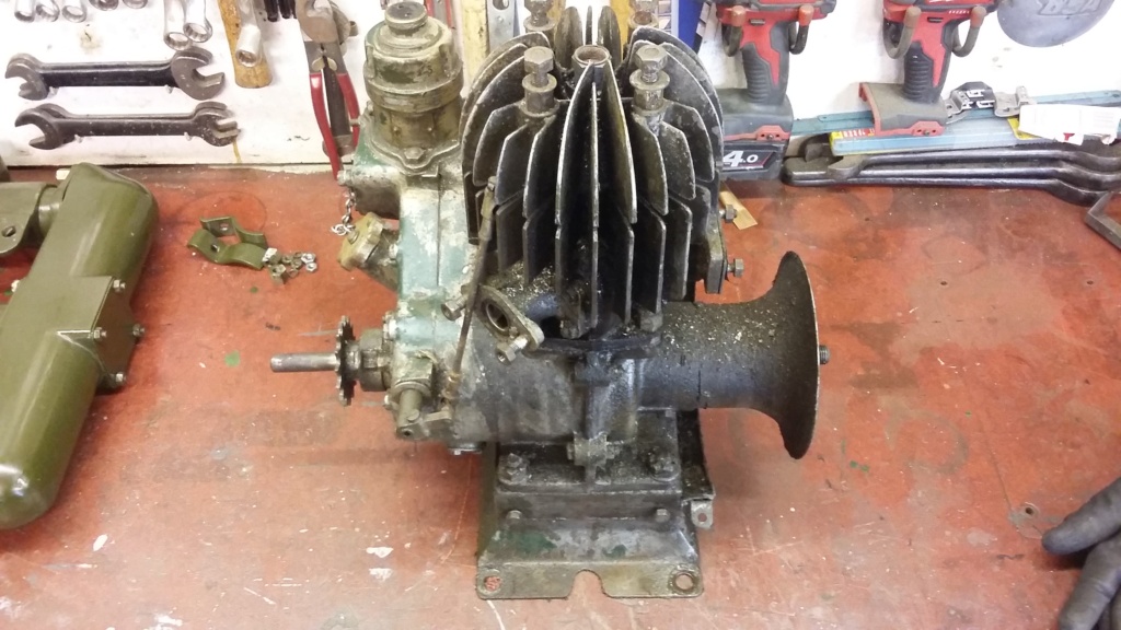
The engine as removed from the set, having had all the cowling taken off. Awaiting its turn in the restoration process.

Commencing the first trial assembly of the engine, with the crank successfully fitted into flywheel side of the crankcase.
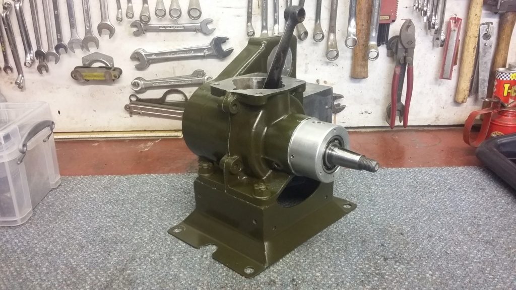
Engine starting to look good with both crankcase halves fitted together. It wasn’t to last!
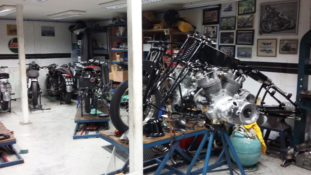
The prestigious company of Vincent motorcycles that the engine was able to keep, whilst having its crank assessed for alignment, as well as having other major engine components checked.
At last my attention was able to turn to the engine rebuild itself, which to some will be seen as the main event, in any restoration project. The engine on this set has never been seen running by myself, so was an unknown quantity and would need to be assessed as the restoration proceeded. With this in mind, I commenced with an initial dry assembly of the crank into the crankcase halves to allow me to judge how all the bearings and seals felt. At first all seemed to go well, with the crank being pressed back into the bearing on the flywheel side crankcase relatively easily, this was followed by the auxiliary drive side, which was equally compliant. At this point the crankshaft was able to rotate very smoothly with the con rod rising under the weight of the counter balance without any other assistance. At this time, the two halves of the crankcase were not bolted together, so this wasn’t not a proper test but was good enough to encourage me to move to the next phase.
As at this stage I was only performing a dry assembly for the purpose of assessing any wear in the bearings or bushes, I had not applied any sealant, so the whole assembly needed to be taken apart again to allow for everything to be properly prepared for final assembly. With the flywheel support bearing in place, the shaft has to be driven or pressed out. As everything had previously gone together quite easily, I thought I could reasonably utilise a soft faced mallet to separate the crank from the case. Unfortunately the bearing had decided to bind onto the shaft, possibly due to a temperature drop and it took more force than I would normally have been happy to use, to achieve separation. With hindsight I should have stopped and either warmed the assembly and or pressed the components apart, instead I continued to drive the shaft out using the mallet. Eventually the crankshaft separation was achieved which allowed me to prepare for the complete unit to once again go through the assembly process but this time with all the sealants and lubrication in place. Once reassembled the two halves were bolted up to allow the sealant to perform its function. It was when the crankcase bolts had been fully tightened that I found that the crank no longer rotated freely for a complete cycle but instead exhibited a tight spot in the same position on every revolution. Thinking the crank may have been pressing against one of the bearings, or the bearing may have moved slightly in their housing, I administered some light taps on either end of the shaft, whilst praying to the engine gods. Unfortunately my prayers weren’t answered, after many light taps followed by some more robust persuasion, the crank continued to bind on every revolution. I concluded that either the binding existed prior to my “intervention” or perhaps more likely the bolted up crank had gone out of alignment due to the harsh treatment.
As I do not possess the equipment or the skills necessary to check and correct crankshaft alignment, I had to look for an engineering company who would be willing and able to undertake this work. After a few false start, I was able to identify a traditional engineering company with a motorcycling background, who were located less than 30 minutes from my home. The crankshaft, crankcase, cylinder and the piston assembly were soon dispatched to be administered to, hopefully to restore the crank to good order and to confirm the state of the rest of the major engine components.
On arrival at the engineering firm I was immediately reassured as to their pedigree and hopefully their abilities. The workshop was fully equipped with a large selection of machine tools and there was a fine selection of exotic motorcycles being worked on. At least the Scott engine would be in the select company of machines from another famous British motorcycling manufacturer, The Vincent!
A nervous wait ensued before I was able to find out what the result of their investigations proved to be……
Neil.

The engine as removed from the set, having had all the cowling taken off. Awaiting its turn in the restoration process.

Commencing the first trial assembly of the engine, with the crank successfully fitted into flywheel side of the crankcase.

Engine starting to look good with both crankcase halves fitted together. It wasn’t to last!

The prestigious company of Vincent motorcycles that the engine was able to keep, whilst having its crank assessed for alignment, as well as having other major engine components checked.
neil (LE)- A credit to the forum

- Posts : 399
Join date : 2012-03-21
Age : 68
Location : N/W Kent
 Re: Scott Generating Set Restoration (Continues)
The crankshaft returns home
I’m back and so is the crank and the other engine parts that went away for assessment and repairs. I should say that the engineering company has not taken all this time to complete the work, it did take them a few weeks but that was to be expected. However it has taken me a lot longer to follow up with a forum update on their assessment and the results of their engineering efforts.
As I surmised in my last post, the main problem was confirmed to be a crank alignment issue, with a runout of 8 thou. This caused the flywheel side, extended crank, to bind in the outrigger flywheel bearing. The crank was trued and refitted into the crankcases to confirm the issue had been resolved, resulting in a smooth rotation of the crank for a full 360 degrees. The crank would now swing around under the weight of the crank webs, allowing the connecting rod to bob up and down as it had previously done.
In addition to the crank, the big end, main bearings and the oilite crankcase seals were also assessed for wear and were passed fit for service, with very little wear being detected. This was a bonus, as it would have been easy for these items to have been identified as worn, or for them to have been recommended to be renewed as a precaution, which would have obviously cost a lot more and taken considerably longer to achieve.
The only other parts that were taken to the engineering company for them to check, were the piston, rings and the cylinder. The cylinder was given a light hone and declared serviceable, the piston and rings were also deemed to be within acceptable tolerances, even though the piston was scored. As the engineer stated, the piston is mainly responsible for carrying the rings and as long there isn’t major damage around the ring grooves the piston can look damaged but be perfectly usable. They did detect slight wear in the small end bush but not enough to be concerned about and suggested it was left alone, especially due to the amount of use the engine will be put to. At worst there might be a small amount of little end rattle, which in reality will be lost amongst the rest of the set noise.
Once I had parted with a very reasonable amount of cash, all the bits were brought home for the engine rebuild to recommence.
With the engine components back on the bench, it was time to decide on how to approach the second attempt at rebuilding the engine. It was tempting to immediately start to reassemble everything but I decided that as there had been some minor damage to the paint finish and there was also a colour match issue, a quick overspray coat was deemed sensible.
Once a suitable amount of time had elapsed, to allow for the paint to dry and harden, the rebuild could once again commence. In an attempt to avoid the issues encountered in the previous rebuild, the build sequence was modified. This time the crank was fitted into the auxiliary drive side crankcase half first. With a little heat applied to the crankcase and the main bearing outer ring, which is retained within the crankcase, the crankshaft with the main bearing fitted, slipped into the crankcase without the need to apply any force. As there isn’t a gasket specified for the crankcase joint, some non-setting sealant was applied, to help to ensure a gas tight seal is achieved.
Before the flywheel side crankcase was offered up to be assembled onto the crankshaft, the outer flywheel bearing was removed. This allowed the two halves to be reunited, using the same method as for the first half, with a little heat and no undue force. The crankcase was then bolted up and everything was checked, to ensure to crank revolved without any tight spots. Once this was successfully demonstrated, the outer bearing was pressed onto the shaft and into its housing. This was followed by a repeat of the rotation test, to conclusively prove the crankshaft binding issue had been resolved.
Having successfully got this far, the rest of the auxiliary drive side of the engine could be reassembled but that is to follow…..
Neil.

The bolted up crankshaft assembly which needed alignment, complete with the original mains and roller big end fitted.

Once home the crankcase halves were given a light coat of paint to repair minor damage following their visit to the engineering workshop and to address a paint colour match issue.
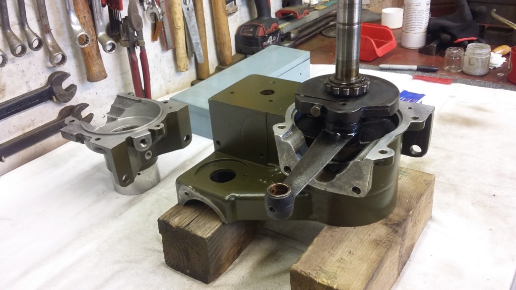
Rebuilding the engine for the second time. This time the crank is fitted to the auxiliary drive side first, to ease the assembly.
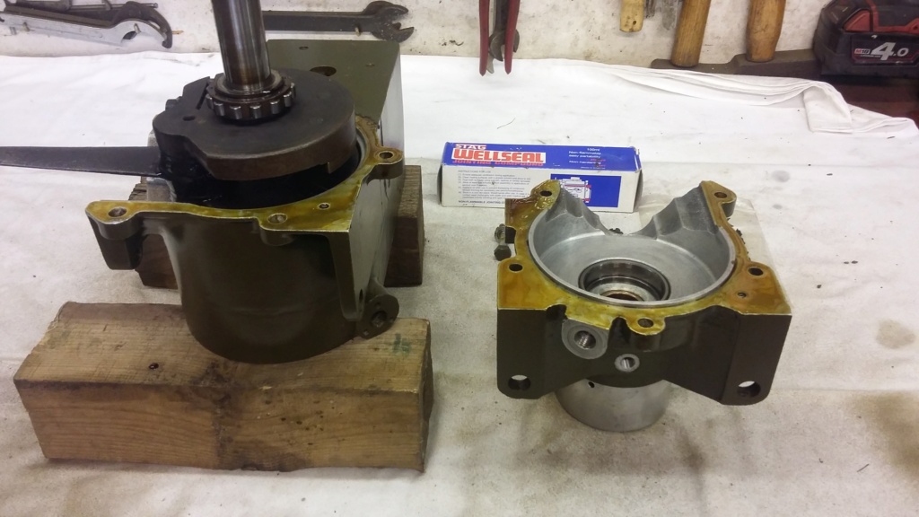
Sealant applied, ready to bring the two halves together. This time the flywheel outrigger bearing has been removed and will be pressed on, once the crankcase has been assembled. This reduces the pressure that needs to be applied during the assembly process, minimising the risk to the crankshaft alignment.
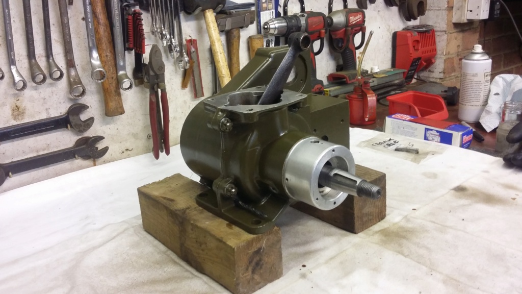
Crankcase fully reassembled, just a new outrigger bearing to be fitted. This time everything rotates as it should (even with the new flywheel bearing fitted), with the connecting rod again rising on its own due to the crank balance weights. Note the drill bit (bottom left) being used as a temporary location dowel. This will be replaced with a proper dowel, or the cut down drill, later.

Engine crankcase assembly stored away, whilst the auxiliary drive case is attended to.
I’m back and so is the crank and the other engine parts that went away for assessment and repairs. I should say that the engineering company has not taken all this time to complete the work, it did take them a few weeks but that was to be expected. However it has taken me a lot longer to follow up with a forum update on their assessment and the results of their engineering efforts.
As I surmised in my last post, the main problem was confirmed to be a crank alignment issue, with a runout of 8 thou. This caused the flywheel side, extended crank, to bind in the outrigger flywheel bearing. The crank was trued and refitted into the crankcases to confirm the issue had been resolved, resulting in a smooth rotation of the crank for a full 360 degrees. The crank would now swing around under the weight of the crank webs, allowing the connecting rod to bob up and down as it had previously done.
In addition to the crank, the big end, main bearings and the oilite crankcase seals were also assessed for wear and were passed fit for service, with very little wear being detected. This was a bonus, as it would have been easy for these items to have been identified as worn, or for them to have been recommended to be renewed as a precaution, which would have obviously cost a lot more and taken considerably longer to achieve.
The only other parts that were taken to the engineering company for them to check, were the piston, rings and the cylinder. The cylinder was given a light hone and declared serviceable, the piston and rings were also deemed to be within acceptable tolerances, even though the piston was scored. As the engineer stated, the piston is mainly responsible for carrying the rings and as long there isn’t major damage around the ring grooves the piston can look damaged but be perfectly usable. They did detect slight wear in the small end bush but not enough to be concerned about and suggested it was left alone, especially due to the amount of use the engine will be put to. At worst there might be a small amount of little end rattle, which in reality will be lost amongst the rest of the set noise.
Once I had parted with a very reasonable amount of cash, all the bits were brought home for the engine rebuild to recommence.
With the engine components back on the bench, it was time to decide on how to approach the second attempt at rebuilding the engine. It was tempting to immediately start to reassemble everything but I decided that as there had been some minor damage to the paint finish and there was also a colour match issue, a quick overspray coat was deemed sensible.
Once a suitable amount of time had elapsed, to allow for the paint to dry and harden, the rebuild could once again commence. In an attempt to avoid the issues encountered in the previous rebuild, the build sequence was modified. This time the crank was fitted into the auxiliary drive side crankcase half first. With a little heat applied to the crankcase and the main bearing outer ring, which is retained within the crankcase, the crankshaft with the main bearing fitted, slipped into the crankcase without the need to apply any force. As there isn’t a gasket specified for the crankcase joint, some non-setting sealant was applied, to help to ensure a gas tight seal is achieved.
Before the flywheel side crankcase was offered up to be assembled onto the crankshaft, the outer flywheel bearing was removed. This allowed the two halves to be reunited, using the same method as for the first half, with a little heat and no undue force. The crankcase was then bolted up and everything was checked, to ensure to crank revolved without any tight spots. Once this was successfully demonstrated, the outer bearing was pressed onto the shaft and into its housing. This was followed by a repeat of the rotation test, to conclusively prove the crankshaft binding issue had been resolved.
Having successfully got this far, the rest of the auxiliary drive side of the engine could be reassembled but that is to follow…..
Neil.

The bolted up crankshaft assembly which needed alignment, complete with the original mains and roller big end fitted.

Once home the crankcase halves were given a light coat of paint to repair minor damage following their visit to the engineering workshop and to address a paint colour match issue.

Rebuilding the engine for the second time. This time the crank is fitted to the auxiliary drive side first, to ease the assembly.

Sealant applied, ready to bring the two halves together. This time the flywheel outrigger bearing has been removed and will be pressed on, once the crankcase has been assembled. This reduces the pressure that needs to be applied during the assembly process, minimising the risk to the crankshaft alignment.

Crankcase fully reassembled, just a new outrigger bearing to be fitted. This time everything rotates as it should (even with the new flywheel bearing fitted), with the connecting rod again rising on its own due to the crank balance weights. Note the drill bit (bottom left) being used as a temporary location dowel. This will be replaced with a proper dowel, or the cut down drill, later.

Engine crankcase assembly stored away, whilst the auxiliary drive case is attended to.
neil (LE)- A credit to the forum

- Posts : 399
Join date : 2012-03-21
Age : 68
Location : N/W Kent
 Re: Scott Generating Set Restoration (Continues)
Lovely stuff, really cheers me up to see such an engine get this treatment.
StuartTurnerSteve- Life Member

- Posts : 534
Join date : 2020-01-02
 Re: Scott Generating Set Restoration (Continues)
Nice work, it must be satisfying to finally get some of it together.
I also put 'sub assemblies' in plastic bags! Keep progressing.
Alan
I also put 'sub assemblies' in plastic bags! Keep progressing.
Alan
Alanengine- A credit to the forum

- Posts : 461
Join date : 2020-11-21
 Re: Scott Generating Set Restoration (Continues)
Thank you gentlemen for your comments. It is great to be making progress and hopefully I'll be in a position, in the not too distant future, to be able to test run the engine. This is always assuming I don't discover, or cause, any further issues as I progress but that's all part of the fun of our hobby!
It may seem ironic but I should say, producing the updates for the forum and the feedback I've received, has defiantly helped to keep the project progressing. It focusses the mind knowing that some time has elapsed since the last forum post and to be able to produce a new one, requires progress to have been made. This in turn spurs me on to continue with next phase of the restoration. Hopefully this is a win win situation which might help to see the project through to a successful conclusion, only time will tell.
Neil.
neil (LE)- A credit to the forum

- Posts : 399
Join date : 2012-03-21
Age : 68
Location : N/W Kent
 Re: Scott Generating Set Restoration (Continues)
Auxiliary Drive Case Rebuild (Including the Governor, Magneto Drive and Starter Dog) Pt. 1
Having completed the main crankcase reassembly, it was the turn of the auxiliary drive case. This unit houses the governor assembly, magneto drive shaft and the starter dog, all of which are linked together and driven from the crankshaft, via a duplex chain.
Before commencing the work of rebuilding the internals, I dealt with an external issue. Due to their poor condition, I needed to replace the governor cross shaft bearings which are housed in the auxiliary drive case casting itself. It seems an odd engineering decision to use ball bearings in these circumstances, as the angle of rotation is no more than a few degrees.
The bearings are located in blind recesses, making it impossible to remove them, by driving them out using the outer bearing ring, as would normally be recommended. It is therefore necessary to remove the bearings, using the inner ring. As I don’t have access to internal expanding bearing extractors, an alternative approach was necessary. I was fortunate, in so much as one of the bearings and its housing was in good condition. This allowed the bearing to be removed relatively easily, with the application of some gentle heat, and tapping until the bearing released itself.
Unfortunately due to corrosion around the bearing recess, the other bearing was less cooperative. However as luck would have it, with the first bearing having been removed, I was able to find a length of studding which exactly fitted the cross shaft tube but didn’t pass through the inner bearing ring. With this in place and having applied both heat and releasing fluids, the bearing was tapped out.
Once the old bearings were out, it was a simple job to press in the new items in to their housings and then pack them with grease. It is interesting to note that these bearings are quite exposed to the elements but there is no provision made for lubrication. That is apart from removing the bearing cap and applying grease around the outside of the bearing, hoping it makes its way into the inner workings. I would imagine that, due to the lack of a full rotation of the bearings and the poor lubrication capabilities, these bearing would have been prone to seizing in their day.
The auxiliary drive internals rebuild to follow…..
Neil.

Governor cross shaft bearing, one of two that needed to be replaced.

The first one was easily removed, using a little heat and then tapped out.
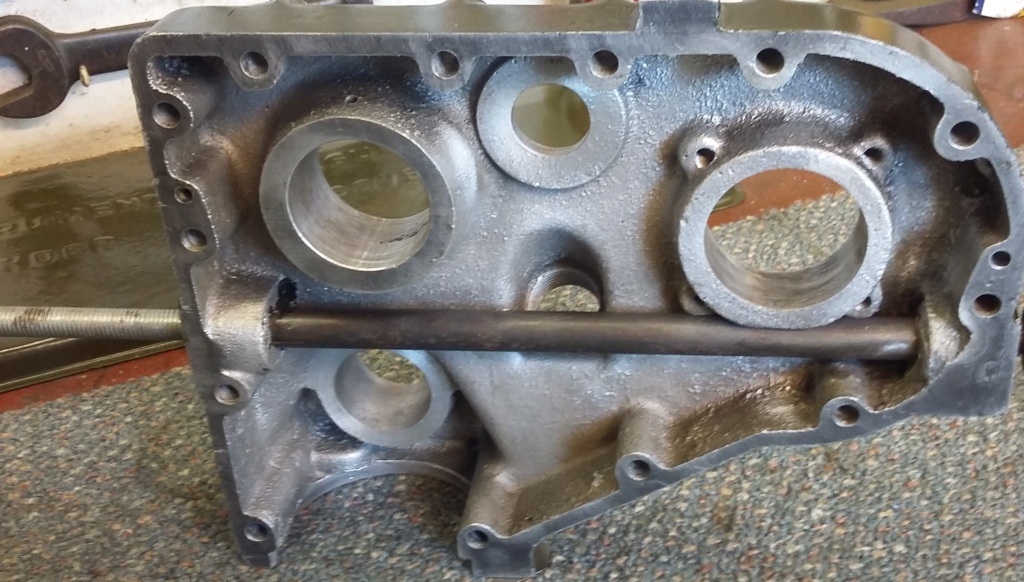
The second bearing initially resisted. A length of studding was used which just fitted the internal sleeve but….
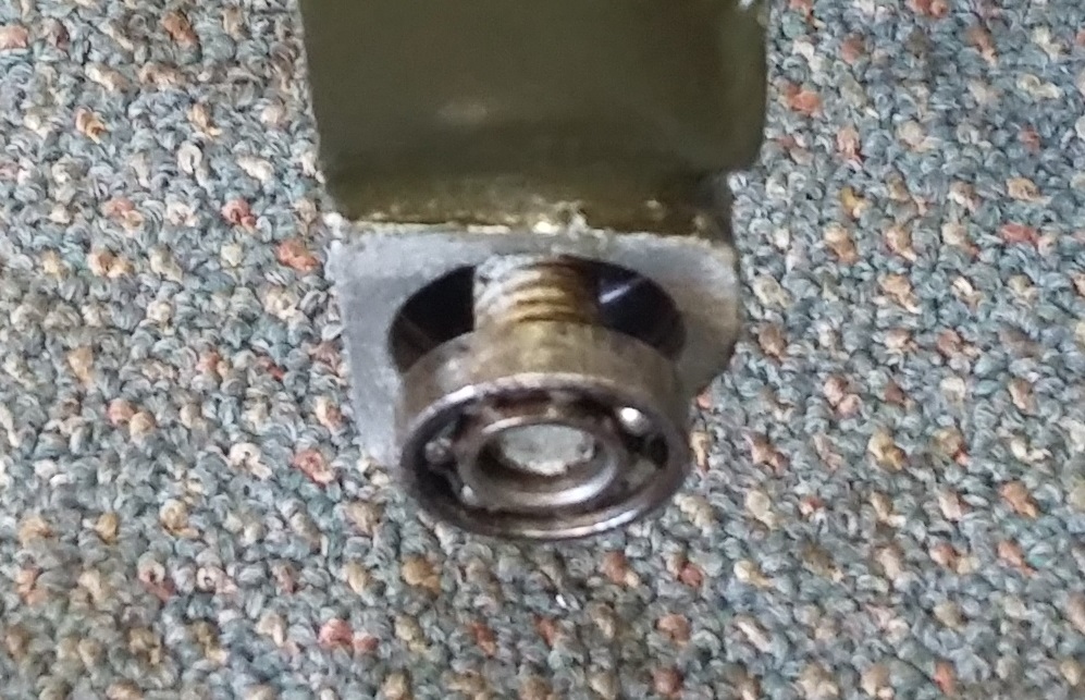
….didn’t pass through the bearing centre….
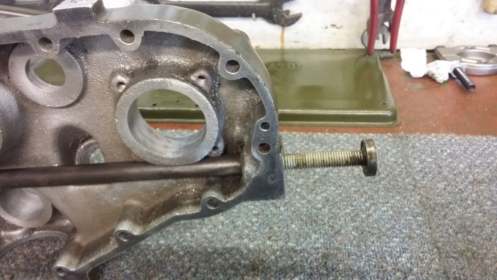
….allowing the bearing to be extracted!
Having completed the main crankcase reassembly, it was the turn of the auxiliary drive case. This unit houses the governor assembly, magneto drive shaft and the starter dog, all of which are linked together and driven from the crankshaft, via a duplex chain.
Before commencing the work of rebuilding the internals, I dealt with an external issue. Due to their poor condition, I needed to replace the governor cross shaft bearings which are housed in the auxiliary drive case casting itself. It seems an odd engineering decision to use ball bearings in these circumstances, as the angle of rotation is no more than a few degrees.
The bearings are located in blind recesses, making it impossible to remove them, by driving them out using the outer bearing ring, as would normally be recommended. It is therefore necessary to remove the bearings, using the inner ring. As I don’t have access to internal expanding bearing extractors, an alternative approach was necessary. I was fortunate, in so much as one of the bearings and its housing was in good condition. This allowed the bearing to be removed relatively easily, with the application of some gentle heat, and tapping until the bearing released itself.
Unfortunately due to corrosion around the bearing recess, the other bearing was less cooperative. However as luck would have it, with the first bearing having been removed, I was able to find a length of studding which exactly fitted the cross shaft tube but didn’t pass through the inner bearing ring. With this in place and having applied both heat and releasing fluids, the bearing was tapped out.
Once the old bearings were out, it was a simple job to press in the new items in to their housings and then pack them with grease. It is interesting to note that these bearings are quite exposed to the elements but there is no provision made for lubrication. That is apart from removing the bearing cap and applying grease around the outside of the bearing, hoping it makes its way into the inner workings. I would imagine that, due to the lack of a full rotation of the bearings and the poor lubrication capabilities, these bearing would have been prone to seizing in their day.
The auxiliary drive internals rebuild to follow…..
Neil.

Governor cross shaft bearing, one of two that needed to be replaced.

The first one was easily removed, using a little heat and then tapped out.

The second bearing initially resisted. A length of studding was used which just fitted the internal sleeve but….

….didn’t pass through the bearing centre….

….allowing the bearing to be extracted!
neil (LE)- A credit to the forum

- Posts : 399
Join date : 2012-03-21
Age : 68
Location : N/W Kent
 Re: Scott Generating Set Restoration (Continues)
Auxiliary Drive Case Rebuild (Including the Governor, Magneto Drive and Starter Dog) Pt. 2
Before I continue with the engine rebuild updates, I should note and acknowledge that there are already two comprehensive threads on this forum, describing an extensive restoration of a Scott PA engine. These posts are with respect to the same engine, which underwent a full restoration by abes and nutgone back in 2012 to 2013. (links attached https://ukengineforum.forumotion.com/t4564-scott-pab-restoration and https://ukengineforum.forumotion.com/t5959-scott-pab-engine-strip-down?highlight=scott). I don’t know of the whereabouts of the engine now but it would be interesting to know if it is still up and running.
Bearing this is mind I might not be as extensive with the engine rebuild section of my restoration but will continue to post updates as to my progress. Hopefully I will not be repeating too much that has already been covered in the previous restoration threads.
Once the cross shaft bearings had been renewed, the first of the internal Item to be tackled was the magneto drive shaft. This is a simple spindle with a large magneto dog drive external to the auxiliary drive case, with a seal and a bearing housed in an external carrier attached to the case. Inside there is a duplex chain cog, keyed onto the shaft at one end of the shaft and a bevel drive gear, for the tachometer and a support bearing at the other. The shaft needs to be stripped of all the keyed on components before it can be removed or inserted through the oil seal and bearing. This process must have been undertaken during the disassembly process, although due to the passage of time I cannot remember exactly how this was achieved. However I had obviously pressed the assembly back together again to keep everything complete. This meant it all had to be stripped again before it could be properly reassembled into the auxiliary case. To do this, I used the recently purchased puller with gear attachment, which made easy work of the process.
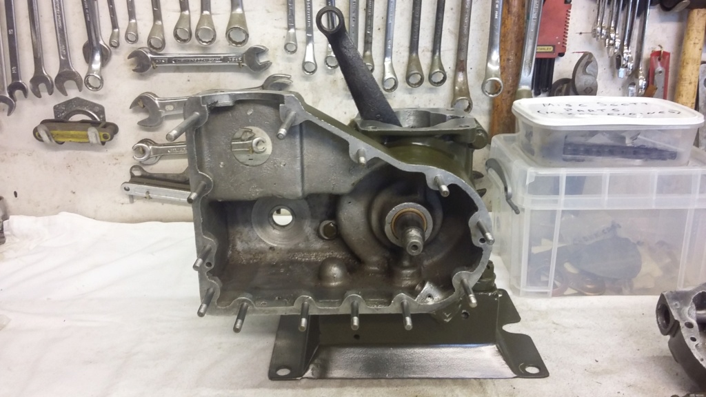
The empty auxiliary drive case awaiting for its internals to be refitted.
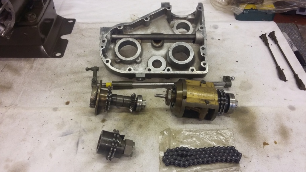
Auxiliary drive case with the separate components awaiting to be refurbished and installed.
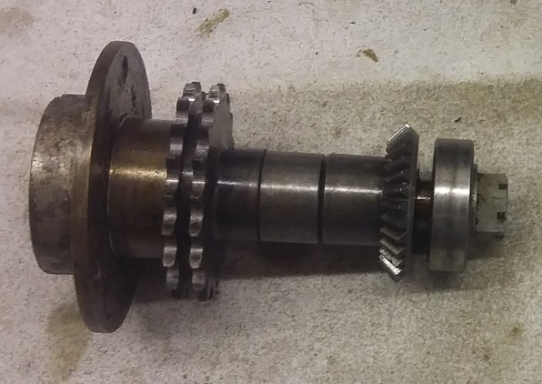
Magneto drive shaft assembly, before being disassembled again, ready to be rebuilt into the auxiliary case.
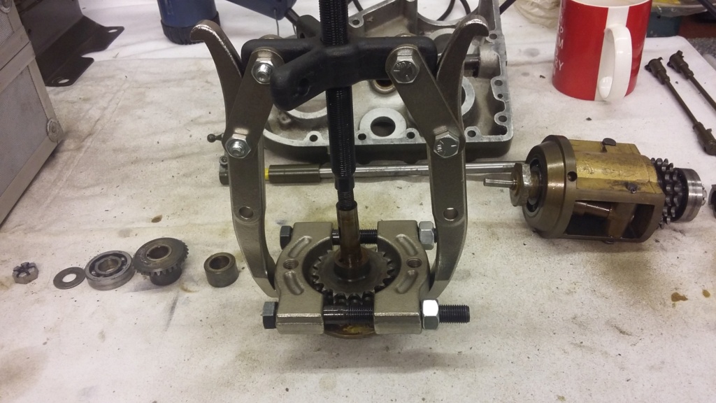
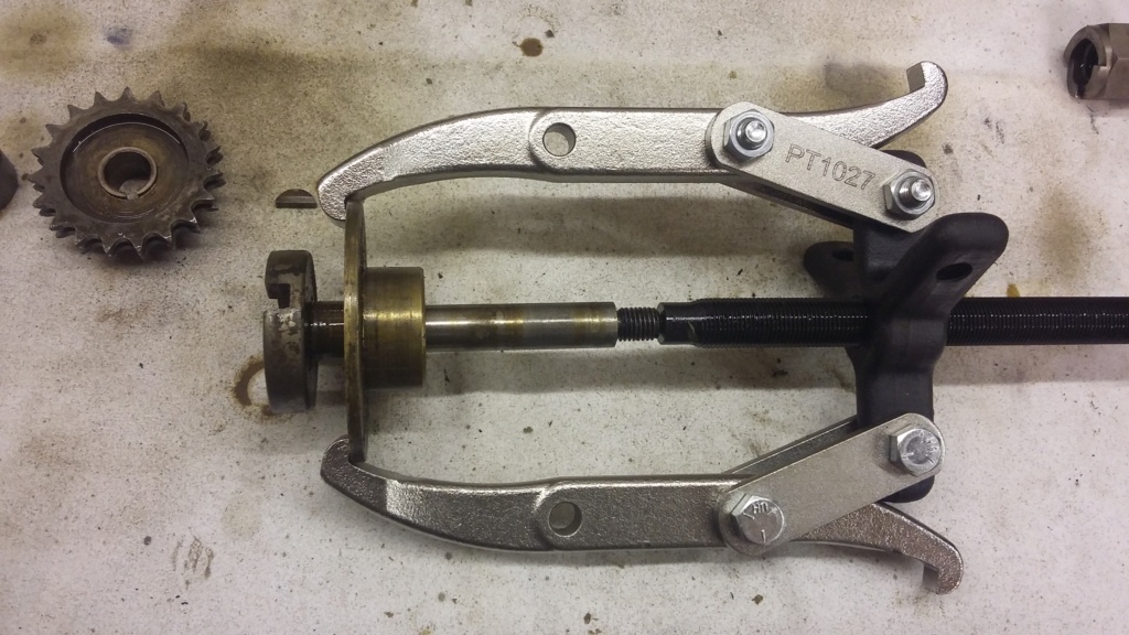
Magneto drive shaft being disassembled. New puller made the job nice and easy.
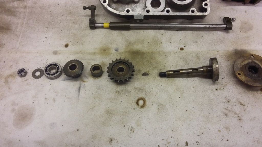
Magneto drive shaft fully disassembled, apart from the bearing and oil seal which are still in the housing.
Once the shaft had been fully stripped down, the bearing and oil seal were removed from the housing with new items being pressed in. The shaft was then carefully slid through the new oil seal and pressed into the bearing in the housing. The bare shaft was then inserted into the auxiliary drive case, allowing the internal items to be refitted to the shaft, including the support bearing, an RLS 4A which wasn’t renewed. With everything replaced on the shaft, the complete assembly is held together using castellated nut and split pin.
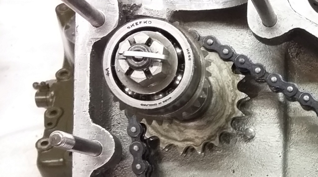
Magneto drive shaft fully reassembled, within the auxiliary drive case.
Following on from the magneto drive shaft, the next item to be tackled was the governor assembly, which by any standards is a large and complex device. This is especially so when the size of the engine is taken into consideration and the fact that this was built during the war and uses materials which were scarce during this period. The main housing is made of brass (bronze?), there are three bearings, as well as a sliding spindle and flyweights fitted with roller balls, all of which necessitated the fine machining of the surfaces, to achieve a smooth action.
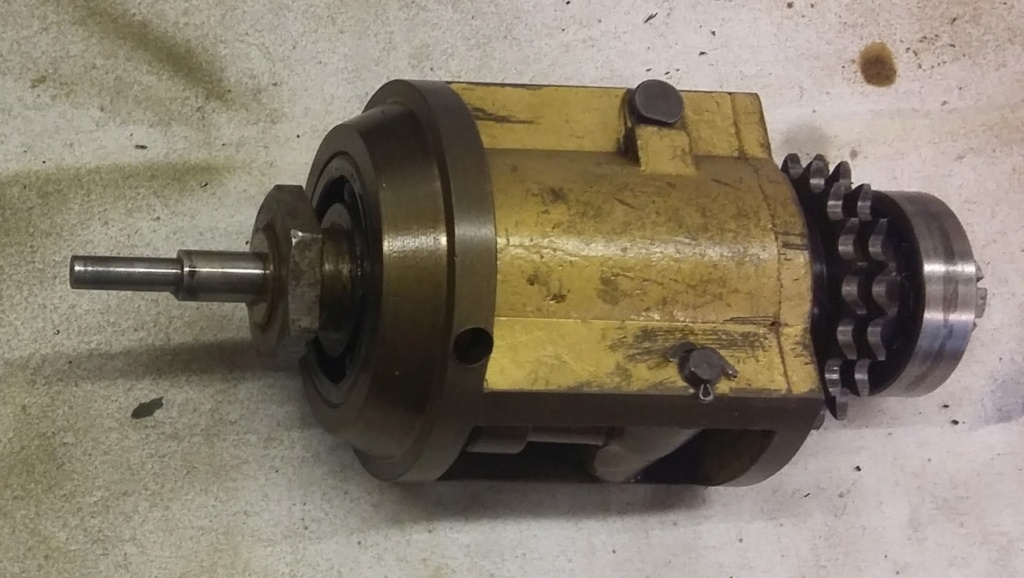
The very substantially made governor assembly, awaiting to be rebuilt.
The general condition of the governor assembly seemed to be very good, with little signs of wear. Even so the opportunity was taken to identify if replacements bearings were available. The originals were SKEFKO now SKF. Unlike most of the other bearings these were metric, the main one in the housing being an RLS 6A with the one on the other end of the shaft being an RLS 5A (RLS 4A is used on the magneto drive shaft). Equivalent bearings for RLS 5 and 6 (and 4) were available but none of the suppliers I contacted could identify what differences, if any, were inferred by the A suffix, (possibly tighter tolerances). As there was no certainty about the replacement items and there was no discernible wear in the old bearings, they were retained and the unit rebuilt with them.
The third bearing is internal to the governor workings and is pressed onto the sliding spindle, being housed in a free cup which bears on the flyweight balls. Although the bearing felt to be in good order, I did find that when the spindle was extended, it was possible for the bearing to be pulled out of the cup, allowing it to become detached and to fall away into the workings. I considered that there were two options. One was to use bearing lock fluid but that could make future disassembly difficult. The second option was to see if a new bearing would be a marginally tighter fit into the cup, making it more secure but easier to take apart again if necessary. The second option was tried and proved to be successful.
The only other bearing items in the governor assembly are on the flyweights. These have roller balls on their ends, which bear on the free bearing cup and the arms have swivel pins to rotate on. As all these seemed to be in good order and couldn’t be easily replaced they were left well alone.
That’s all for now, so may I wish you all a Merry Christmas and a safe, healthy and Happy New Year.
Hopefully more to come next year…..
Neil.

Governor sliding shaft (L) with bearing attached, housed in a free cup.
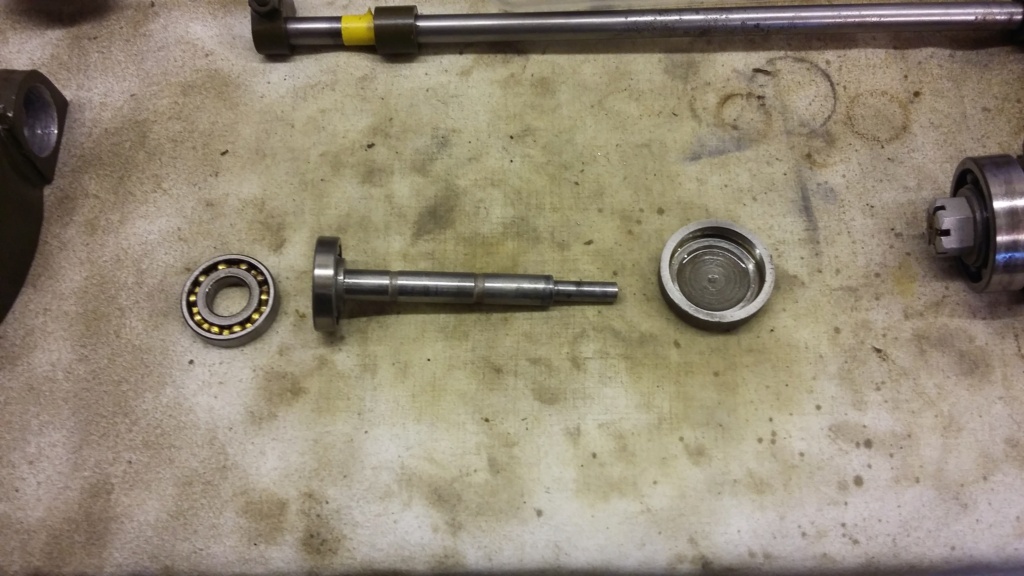
The sliding spindle with the new bearing pressed on, the old one to the left and the cup to the right.

A variety of parts, including the main governor items during the rebuild process.

The main bearing RLS 6A, in the process of being refitted….
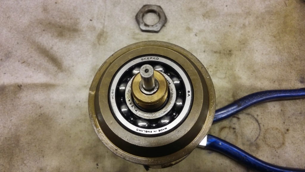
….then fully refitted, ready for continued service.
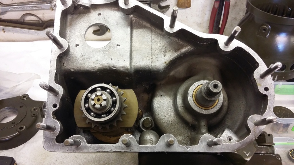
Rebuilt governor being test fitted into the auxiliary case. Split pin still to be fitted.
Before I continue with the engine rebuild updates, I should note and acknowledge that there are already two comprehensive threads on this forum, describing an extensive restoration of a Scott PA engine. These posts are with respect to the same engine, which underwent a full restoration by abes and nutgone back in 2012 to 2013. (links attached https://ukengineforum.forumotion.com/t4564-scott-pab-restoration and https://ukengineforum.forumotion.com/t5959-scott-pab-engine-strip-down?highlight=scott). I don’t know of the whereabouts of the engine now but it would be interesting to know if it is still up and running.
Bearing this is mind I might not be as extensive with the engine rebuild section of my restoration but will continue to post updates as to my progress. Hopefully I will not be repeating too much that has already been covered in the previous restoration threads.
Once the cross shaft bearings had been renewed, the first of the internal Item to be tackled was the magneto drive shaft. This is a simple spindle with a large magneto dog drive external to the auxiliary drive case, with a seal and a bearing housed in an external carrier attached to the case. Inside there is a duplex chain cog, keyed onto the shaft at one end of the shaft and a bevel drive gear, for the tachometer and a support bearing at the other. The shaft needs to be stripped of all the keyed on components before it can be removed or inserted through the oil seal and bearing. This process must have been undertaken during the disassembly process, although due to the passage of time I cannot remember exactly how this was achieved. However I had obviously pressed the assembly back together again to keep everything complete. This meant it all had to be stripped again before it could be properly reassembled into the auxiliary case. To do this, I used the recently purchased puller with gear attachment, which made easy work of the process.

The empty auxiliary drive case awaiting for its internals to be refitted.

Auxiliary drive case with the separate components awaiting to be refurbished and installed.

Magneto drive shaft assembly, before being disassembled again, ready to be rebuilt into the auxiliary case.


Magneto drive shaft being disassembled. New puller made the job nice and easy.

Magneto drive shaft fully disassembled, apart from the bearing and oil seal which are still in the housing.
Once the shaft had been fully stripped down, the bearing and oil seal were removed from the housing with new items being pressed in. The shaft was then carefully slid through the new oil seal and pressed into the bearing in the housing. The bare shaft was then inserted into the auxiliary drive case, allowing the internal items to be refitted to the shaft, including the support bearing, an RLS 4A which wasn’t renewed. With everything replaced on the shaft, the complete assembly is held together using castellated nut and split pin.

Magneto drive shaft fully reassembled, within the auxiliary drive case.
Following on from the magneto drive shaft, the next item to be tackled was the governor assembly, which by any standards is a large and complex device. This is especially so when the size of the engine is taken into consideration and the fact that this was built during the war and uses materials which were scarce during this period. The main housing is made of brass (bronze?), there are three bearings, as well as a sliding spindle and flyweights fitted with roller balls, all of which necessitated the fine machining of the surfaces, to achieve a smooth action.

The very substantially made governor assembly, awaiting to be rebuilt.
The general condition of the governor assembly seemed to be very good, with little signs of wear. Even so the opportunity was taken to identify if replacements bearings were available. The originals were SKEFKO now SKF. Unlike most of the other bearings these were metric, the main one in the housing being an RLS 6A with the one on the other end of the shaft being an RLS 5A (RLS 4A is used on the magneto drive shaft). Equivalent bearings for RLS 5 and 6 (and 4) were available but none of the suppliers I contacted could identify what differences, if any, were inferred by the A suffix, (possibly tighter tolerances). As there was no certainty about the replacement items and there was no discernible wear in the old bearings, they were retained and the unit rebuilt with them.
The third bearing is internal to the governor workings and is pressed onto the sliding spindle, being housed in a free cup which bears on the flyweight balls. Although the bearing felt to be in good order, I did find that when the spindle was extended, it was possible for the bearing to be pulled out of the cup, allowing it to become detached and to fall away into the workings. I considered that there were two options. One was to use bearing lock fluid but that could make future disassembly difficult. The second option was to see if a new bearing would be a marginally tighter fit into the cup, making it more secure but easier to take apart again if necessary. The second option was tried and proved to be successful.
The only other bearing items in the governor assembly are on the flyweights. These have roller balls on their ends, which bear on the free bearing cup and the arms have swivel pins to rotate on. As all these seemed to be in good order and couldn’t be easily replaced they were left well alone.
That’s all for now, so may I wish you all a Merry Christmas and a safe, healthy and Happy New Year.
Hopefully more to come next year…..
Neil.

Governor sliding shaft (L) with bearing attached, housed in a free cup.

The sliding spindle with the new bearing pressed on, the old one to the left and the cup to the right.

A variety of parts, including the main governor items during the rebuild process.

The main bearing RLS 6A, in the process of being refitted….

….then fully refitted, ready for continued service.

Rebuilt governor being test fitted into the auxiliary case. Split pin still to be fitted.
Last edited by neil (LE) on Tue Dec 21 2021, 21:34; edited 1 time in total (Reason for editing : Photo resizing test)
neil (LE)- A credit to the forum

- Posts : 399
Join date : 2012-03-21
Age : 68
Location : N/W Kent
 Re: Scott Generating Set Restoration (Continues)
Auxiliary Drive Case Rebuild (Including the Governor, Magneto Drive and Starter Dog) Pt. 3
Duplex Chain issues.
Before I start, may I wish everyone a happy and healthy New Year. Let’s hope we will all be able to continue to enjoy our hobby, with the full resumption of the rally calendar.
Having completed the strip down and rebuild of the major individual internal components, it was time to proceed to the next phase, the full and hopefully final rebuild of the auxiliary drive case. Before each individual assembly can be bolted up into the case, the duplex chain, linking the drive together needs to be considered. The chain as fitted, is of the endless type and has a 5/16” (8mm) pitch, which is relatively light in construction. Being endless, the chain has to be placed over each of the duplex sprockets prior to them being fully fitted in the case. I remember it being quite a struggle to extract the chain during the strip down process. Although the crankshaft drive dog is retained by a taper shaft, even with this slackened off, it is not possible to pull it far enough forward to allow it to disengage from the shaft, without putting severe strain on the chain. The only way I found to fit the chain, was to leave the magneto drive shaft and the governor assembly loose. This provided sufficient lateral movement to allow the chain to be placed over the three sprockets without straining the chain. With the chain on, the governor and the magneto drive bearing carrier were tightened up, bringing everything into alignment. Once fitted, the chain was obviously very slack, therefore before any assessment could be made as to how worn the chain was, the tensioner had to be fitted.
The tensioner is constructed from a blade of sprung steel anchored at one end, with the other attached to a sliding piston in a tube, which bears against a compression spring held in place by an external plate. The most difficult item to fit was the anchor plate, which is held in place by two drilled 2BA bolts fitted directly through the base of the case with no provision for sealing the fitting, so some non-setting sealant was applied. Access is quite difficult due to the lack of space and once the nuts have been attached and tightened up, split pins are fitted to ensure the nuts stay attached. Due to their size, aligning the drillings in the bolts with the castellation and inserting the very small split pin is, to say the least, a challenge.
With the tensioner fitted the extent of the chain stretch could be estimated. It should be noted that the chain will not be under the correct tension until the auxiliary cover has been fitted. There will be a slight amount of play in the magneto shaft and the governor, until their bearings are held in the outer case. This makes it impossible to properly assess the actual movement on the tensioner, as it cannot be seen once the cover is fitted.
Initially it was thought the amount of movement on the tensioner, indicated potentially excessive wear in the chain. Replacement chains were researched with Renold chains being identified as a possible supplier, unfortunately their chain only seemed to be available in 5 metre lengths, as were many other suppliers. In the end the only possibility was to purchase a 1 metre length of an unspecified UK manufactured chain. Although the pitch and width were correct, the side stretchers were of a larger dimension. This meant that the clearance around the drive sprocket and between it and the tensioner was reduced, possibly to the extent that there was a risk of the chain and the tensioner, when fully extended, clashing.
Having reflected on the pros and cons, I decided to refit the original chain as there didn’t seem to be any slack on the chain once correctly fitted. Although it is impossible to see the chain tensioner once the cover is fitted, it is possible to feel for chain tension through the oil filler hole. Using this approach, I was able to confirm there was still tension being applied to the chain, with some movement still left in the tensioner.
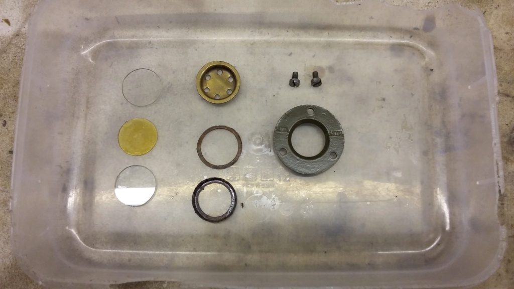
One of the last items to be prepared before the auxiliary case was completed, was the oil level indication window. This comprises a frame, two pieces of glass separated by a sheet of mica and a reflector. The complete unit is held in place by three 4BA screws. Unfortunately one of the threads was already stripped and the screw missing and will need to be resolved before filling the auxiliary case with oil, as the threaded hole penetrates the case. The only other issue was, one of the pieces of glass as fitted, was cracked. Fortunately I had a spare one, unfortunately that one cracked when attempting to screw the unit into the case. This was most probably due tightening up with one of the screws missing, straining the glass. I will consider replacing the two pieces of glass and the mica separator with a single piece of Perspex or equivalent.
That is as far as this update will go, more to follow…..
Neil.
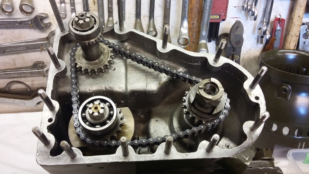
Duplex chain test fitted on the three drive sprockets.

Chain tensioner fitted. The base plate is anchored by bolts which pass directly through the base of the case, without any gasket or sealing provision. Non-setting sealant was applied to the bolts and the base plate to reduce the risk of oil leaks.

Chain adjuster almost fully extended. Grub screw limits its travel to ensure it doesn’t foul the chain. Thread lock has been applied to the grub screw make sure it stays in place!
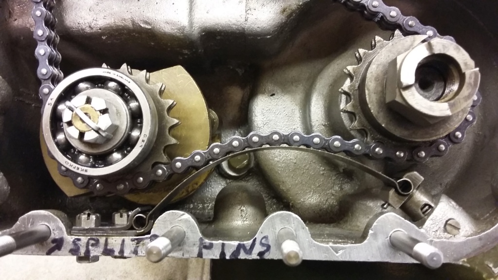
Full extent of the chain curvature over the tensioner, possibly indicating some stretching has occurred. The “split pins” marking is a reminder to insert pins into the tensioner base plate fixings, prior to final assembly of the auxiliary case. Split pin fitting was eventually achieved!

Original chain wrapped around the drive sprocket.

Potential replacement chain also around the drive sprocket. Note how much deeper the chain sits on the sprocket due to the larger dimension of the link plates. This increases the risk of the chain fouling on the tensioner, therefore the original chain will be retained.
The oil level indicator window components being prepared. Note there were only two screws fitted, due to one thread being stripped.
The almost complete auxiliary case fitted to the crankcase. Just the fixings to be painted and the oil level window issues to be resolved.
Duplex Chain issues.
Before I start, may I wish everyone a happy and healthy New Year. Let’s hope we will all be able to continue to enjoy our hobby, with the full resumption of the rally calendar.
Having completed the strip down and rebuild of the major individual internal components, it was time to proceed to the next phase, the full and hopefully final rebuild of the auxiliary drive case. Before each individual assembly can be bolted up into the case, the duplex chain, linking the drive together needs to be considered. The chain as fitted, is of the endless type and has a 5/16” (8mm) pitch, which is relatively light in construction. Being endless, the chain has to be placed over each of the duplex sprockets prior to them being fully fitted in the case. I remember it being quite a struggle to extract the chain during the strip down process. Although the crankshaft drive dog is retained by a taper shaft, even with this slackened off, it is not possible to pull it far enough forward to allow it to disengage from the shaft, without putting severe strain on the chain. The only way I found to fit the chain, was to leave the magneto drive shaft and the governor assembly loose. This provided sufficient lateral movement to allow the chain to be placed over the three sprockets without straining the chain. With the chain on, the governor and the magneto drive bearing carrier were tightened up, bringing everything into alignment. Once fitted, the chain was obviously very slack, therefore before any assessment could be made as to how worn the chain was, the tensioner had to be fitted.
The tensioner is constructed from a blade of sprung steel anchored at one end, with the other attached to a sliding piston in a tube, which bears against a compression spring held in place by an external plate. The most difficult item to fit was the anchor plate, which is held in place by two drilled 2BA bolts fitted directly through the base of the case with no provision for sealing the fitting, so some non-setting sealant was applied. Access is quite difficult due to the lack of space and once the nuts have been attached and tightened up, split pins are fitted to ensure the nuts stay attached. Due to their size, aligning the drillings in the bolts with the castellation and inserting the very small split pin is, to say the least, a challenge.
With the tensioner fitted the extent of the chain stretch could be estimated. It should be noted that the chain will not be under the correct tension until the auxiliary cover has been fitted. There will be a slight amount of play in the magneto shaft and the governor, until their bearings are held in the outer case. This makes it impossible to properly assess the actual movement on the tensioner, as it cannot be seen once the cover is fitted.
Initially it was thought the amount of movement on the tensioner, indicated potentially excessive wear in the chain. Replacement chains were researched with Renold chains being identified as a possible supplier, unfortunately their chain only seemed to be available in 5 metre lengths, as were many other suppliers. In the end the only possibility was to purchase a 1 metre length of an unspecified UK manufactured chain. Although the pitch and width were correct, the side stretchers were of a larger dimension. This meant that the clearance around the drive sprocket and between it and the tensioner was reduced, possibly to the extent that there was a risk of the chain and the tensioner, when fully extended, clashing.
Having reflected on the pros and cons, I decided to refit the original chain as there didn’t seem to be any slack on the chain once correctly fitted. Although it is impossible to see the chain tensioner once the cover is fitted, it is possible to feel for chain tension through the oil filler hole. Using this approach, I was able to confirm there was still tension being applied to the chain, with some movement still left in the tensioner.
One of the last items to be prepared before the auxiliary case was completed, was the oil level indication window. This comprises a frame, two pieces of glass separated by a sheet of mica and a reflector. The complete unit is held in place by three 4BA screws. Unfortunately one of the threads was already stripped and the screw missing and will need to be resolved before filling the auxiliary case with oil, as the threaded hole penetrates the case. The only other issue was, one of the pieces of glass as fitted, was cracked. Fortunately I had a spare one, unfortunately that one cracked when attempting to screw the unit into the case. This was most probably due tightening up with one of the screws missing, straining the glass. I will consider replacing the two pieces of glass and the mica separator with a single piece of Perspex or equivalent.
That is as far as this update will go, more to follow…..
Neil.

Duplex chain test fitted on the three drive sprockets.

Chain tensioner fitted. The base plate is anchored by bolts which pass directly through the base of the case, without any gasket or sealing provision. Non-setting sealant was applied to the bolts and the base plate to reduce the risk of oil leaks.

Chain adjuster almost fully extended. Grub screw limits its travel to ensure it doesn’t foul the chain. Thread lock has been applied to the grub screw make sure it stays in place!

Full extent of the chain curvature over the tensioner, possibly indicating some stretching has occurred. The “split pins” marking is a reminder to insert pins into the tensioner base plate fixings, prior to final assembly of the auxiliary case. Split pin fitting was eventually achieved!

Original chain wrapped around the drive sprocket.

Potential replacement chain also around the drive sprocket. Note how much deeper the chain sits on the sprocket due to the larger dimension of the link plates. This increases the risk of the chain fouling on the tensioner, therefore the original chain will be retained.

The oil level indicator window components being prepared. Note there were only two screws fitted, due to one thread being stripped.

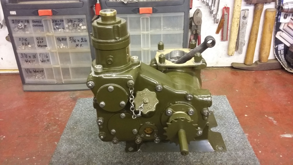
The almost complete auxiliary case fitted to the crankcase. Just the fixings to be painted and the oil level window issues to be resolved.
neil (LE)- A credit to the forum

- Posts : 399
Join date : 2012-03-21
Age : 68
Location : N/W Kent
 Re: Scott Generating Set Restoration (Continues)
Small End Bush, Piston and Cylinder Rebuild. (It’s not always straight forward)
I’ll start this long overdue update with an apology for the length of time that has elapsed since the last project post. The lack of information doesn’t mean that nothing is happening. It is more down to the limited opportunities to make progress, due to time, weather and domestic constraints, resulting in small incremental progress being made. This work didn’t necessarily warrant individual updates and may have lacked any interesting detail. However I now realise there has been sufficient progress made and issues encountered to inspire me to provide an update.
Having basically completed the crankcase reassembly it was time to replace the piston and fit the cylinder. This was thought to be a quick and easy task to complete, hopefully leading to the possibility of a test run. Unfortunately for various reasons, things did not turn out to be that simple. Do they ever?
The first issue to be encountered was the small end bush retaining screw. To ensure the bush cannot rotate in the con-rod end, thereby blocking the four lubrication holes, a small countersunk grub screw is fitted. On checking through the bagged up parts, there was no sign of the offending screw. This meant I had either misplaced it, which seemed unlikely as everything had been packed away carefully, or it was missing before the engine was disassembled. Had the screw been deleted from the design due to the risk of damage if it were to be dislodged and had its function been replaced by the use of an interference fit reamed bush? Without being certain that the bush was now an interference fit, if the screw wasn’t fitted, then there was a risk that the bush which although seemed to be tight, might become loose through expansion, when the engine warmed up. Having considered the options the decision was taken to refit a locking screw, just to be on the safe side. The original fitting was a 3mm long 5BA countersunk screw, not having a suitable replacement, a selection of 5BA screws were acquired. Unfortunately once received and tried, they were found to be too small for the threaded hole. When checked there was clearance for a 5 BA tapping drill to pass straight through. In the end, the best option seemed to be to tap the thread out for a larger sized BA screw. This resulted in the countersink head not exactly fitting in the chamfer in the con-rod but that was not a concern as there was plenty of space available to accommodate the larger head size. It could easily be seen that the original screw had been punched to ensure it was retained, this was done to the new screw, as well as using some thread lock.
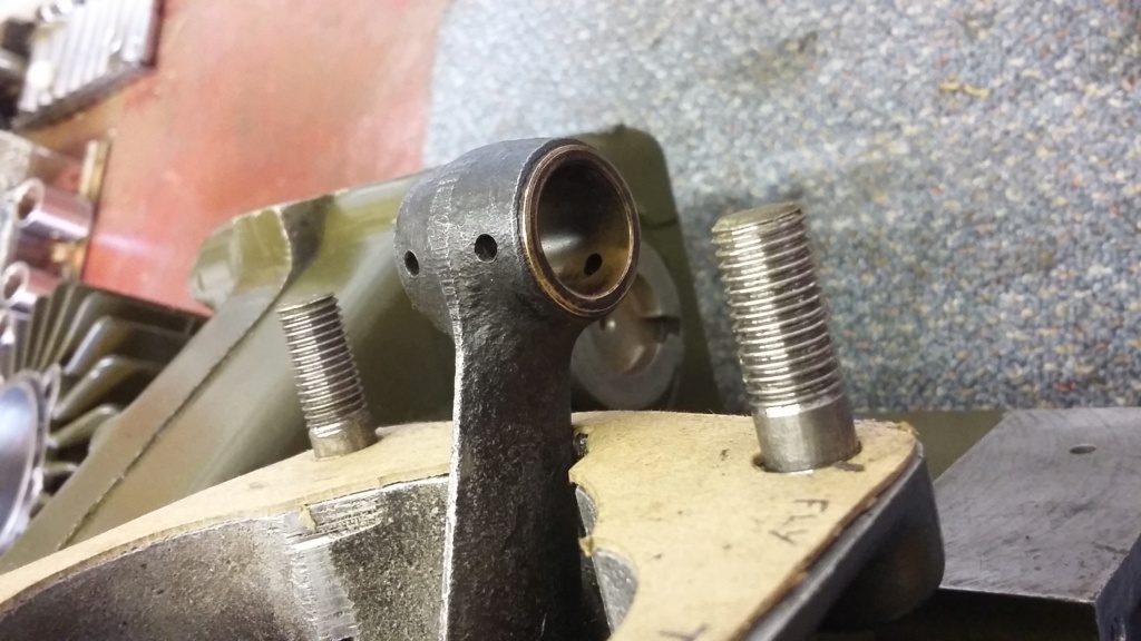
The small end oil holes which must remain aligned.
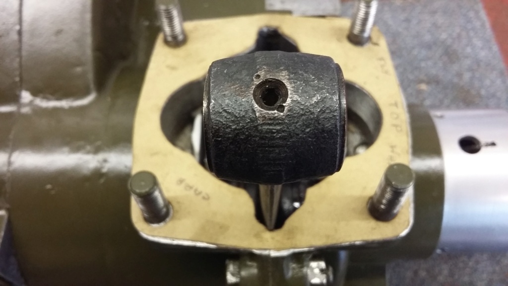
Countersunk threaded hole for the locking grub screw. Note the dot punch marks which had been used to retain screw.
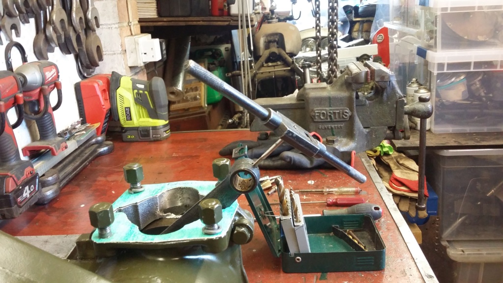
Small end bush locking screw thread being tapped out to a larger size.

New larger locking screw.
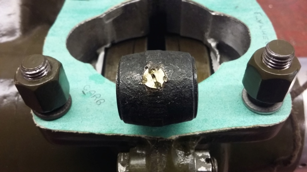
Replacement screw fitted and pin punched.
Once the small end bush situation was resolved it should have been a simple task to rebuild the rest of the engine, ready for initial testing. Unfortunately this hasn’t turned out to be the case.
The piston was simply refitted to the con-rod, ensuring the blanked off end of the gudgeon pin was opposite the exhaust port, as detailed in the manual. I’m not certain what the importance of this is, does anyone know? After a new cylinder base gasket was cut out and fitted, the cylinder was gently eased back over the piston and rings, ready to be bolted down. In fact the gasket used was the second one made, as I wasn’t fully happy with the quality of the material of the first one, making the second one from Klingersil sheet. The relevance of this will become clear later. No torque settings are known but as I have suffered with the cylinder base mountings coming loose, I have used split washers and have tightened down quiet firmly. Hopefully this will be sufficient to ensure they do not work loose.
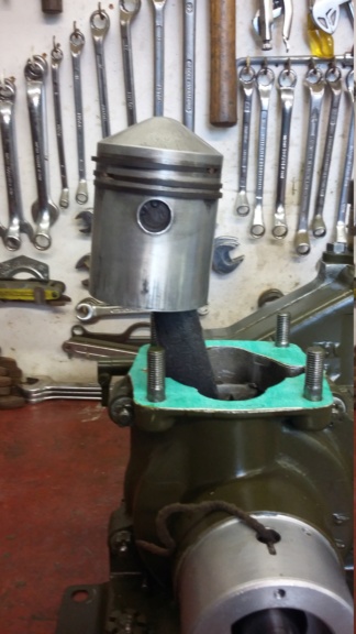
Blanked off end of the gudgeon pin.
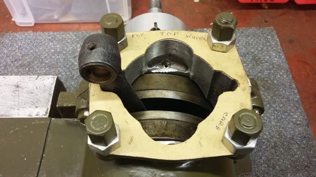
First cylinder base gasket being produced.
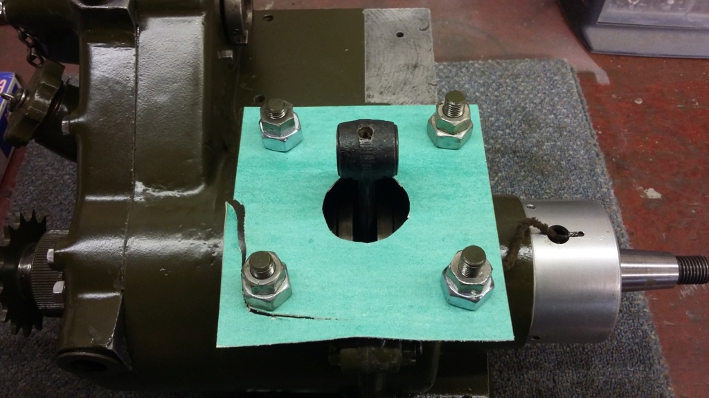
Second base gasket being cut from Klingersil sheet.
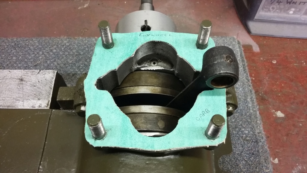
Second gasket as originally fitted.
The cylinder head to barrel joint does not have a gasket but has a stepped spigot to help seal the joint. Some Wellseal was applied and the head simply fitted with the four fixings, again just using feel to judge the tightness of the nuts. Once fitted with the flywheel attached, the engine was turned over without the plug in, to confirm everything felt good. To my dismay the engine rotated around about 359 degrees when it stopped. Luckily it was only being turned slowly so there was little chance of damage to whatever was causing it. On turning the engine backwards the same thing happened. With the head removed it could be seen that the piston edge was just proud of the cylinder wall, causing the piston to hit the head I initially assumed it was the base gasket that was not thick enough, causing the piston to foul on the head. Nothing for it, the engine had to be taken apart again and a thicker base gasket fitted. As I didn’t have any thicker material available, the first gasket which had been produced was fitted with the second, just to see if this resolved the situation. Once again the engine was rebuilt with the two gaskets in place, the engine was turned over to confirm that a full rotation could be achieved. Having successfully spun the engine over, without any issues the next phase was to check there was at least some compression. A compression tester provided a reading of approximately 80 P.S.I. seemingly an acceptable level.
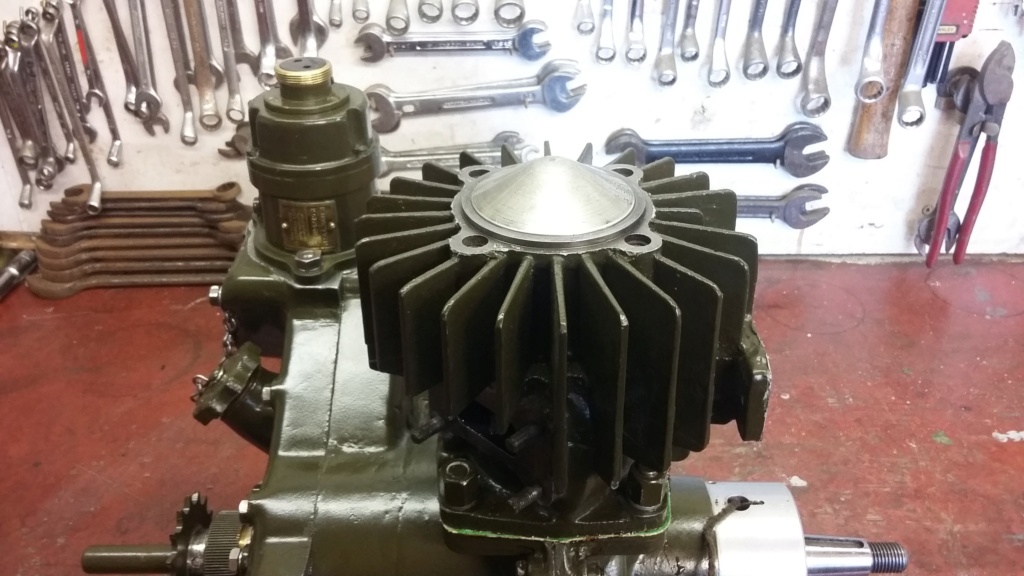
Piston sitting just proud of the cylinder causing it to foul the head.
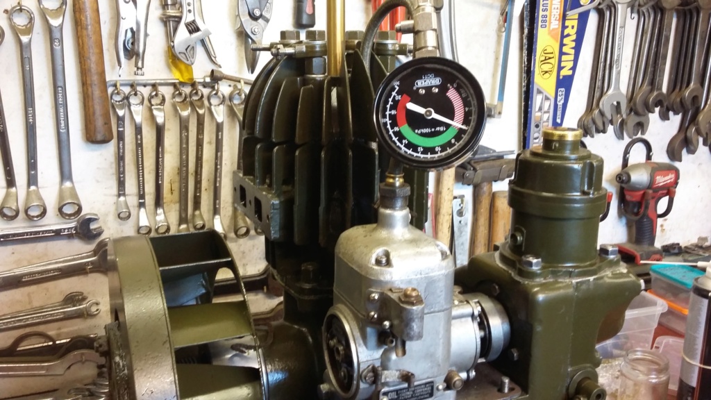
Compression test reading, once the two base gaskets had been fitted to allow the engine to turn over without fouling.
I’ll leave it there for now but there are more frustrations to follow.
Neil.
neil (LE)- A credit to the forum

- Posts : 399
Join date : 2012-03-21
Age : 68
Location : N/W Kent
 Re: Scott Generating Set Restoration (Continues)
It's amazing that something that should be 'straightforward' assembly doesn't go to plan!
We've all been there but progress is progress, nice to see it's coming along though.
Alan
We've all been there but progress is progress, nice to see it's coming along though.
Alan
Alanengine- A credit to the forum

- Posts : 461
Join date : 2020-11-21
 Re: Scott Generating Set Restoration (Continues)
Is there definitely no seal for the head? My Tarpen engine has a spigot like that but there was a sealing ring in the recess in the head.
_________________
Specialist in precision guesswork.

mattblack- Life Member

- Posts : 889
Join date : 2019-06-21
Location : Leicester, me duck...
 Re: Scott Generating Set Restoration (Continues)
Thanks for the comments. Yes it is frustrating how things can conspire to cause difficulties on the simplest of procedures. As you will see in the next post, the gremlins are not done with me yet!
Mattblack, I agree that if there was a gasket this could relieve the problem, however there is not one shown in the parts list, nor is one mentioned in the servicing instructions. As you will see in the next post, I believe there was a more fundamental reason for the issue.
Neil
Mattblack, I agree that if there was a gasket this could relieve the problem, however there is not one shown in the parts list, nor is one mentioned in the servicing instructions. As you will see in the next post, I believe there was a more fundamental reason for the issue.
Neil
neil (LE)- A credit to the forum

- Posts : 399
Join date : 2012-03-21
Age : 68
Location : N/W Kent
 Re: Scott Generating Set Restoration (Continues)
Small End Bush, Piston and Cylinder Rebuild. Pt. 2 (It’s still not straight forward)
Having ascertained a thicker base gasket seemed to resolve the issue, I had resigned myself to disassembling the engine once again. However before I got that far, I noticed that something wasn’t right with the cylinder head. When turning the engine over with the plug in, there were indications of compression leaking around the spark plug hole. On closer examination, there was an unexplained drilled hole around the edge of the threaded in plug insert, through which air could be seen to be escaping. Having removed the head to take a closer look it became apparent that not only was the head leaking around the insert but also the cylinder head had been heavily skimmed, which I believed was also causing the piston to clash with the head.
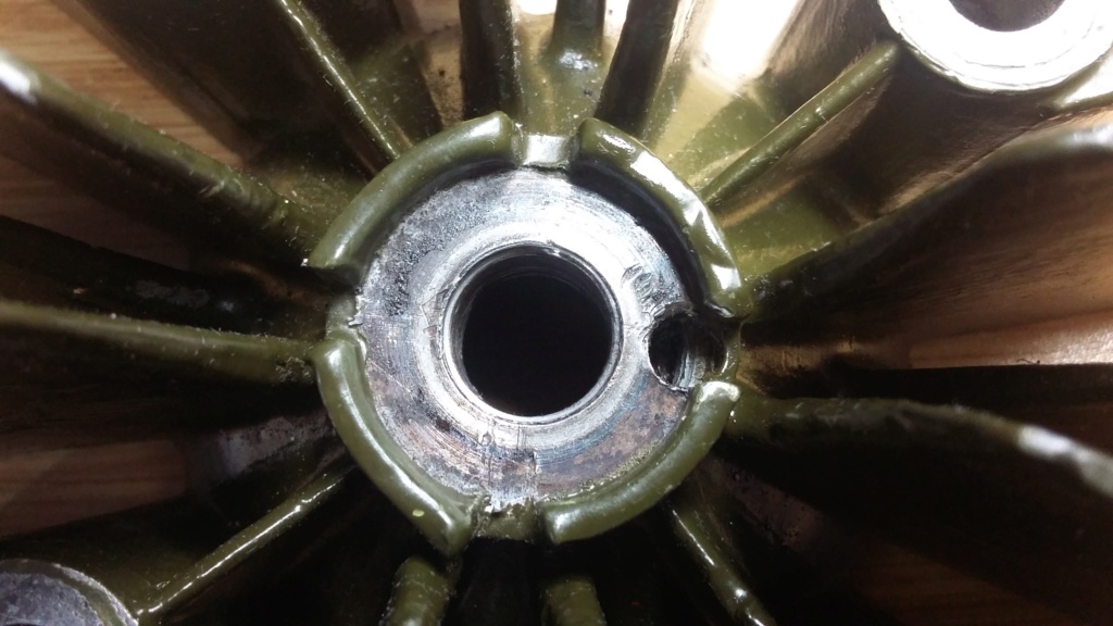
Unexplained drilling in the spark plug threaded insert. This allowed air to leak around the thread and out of the hole.
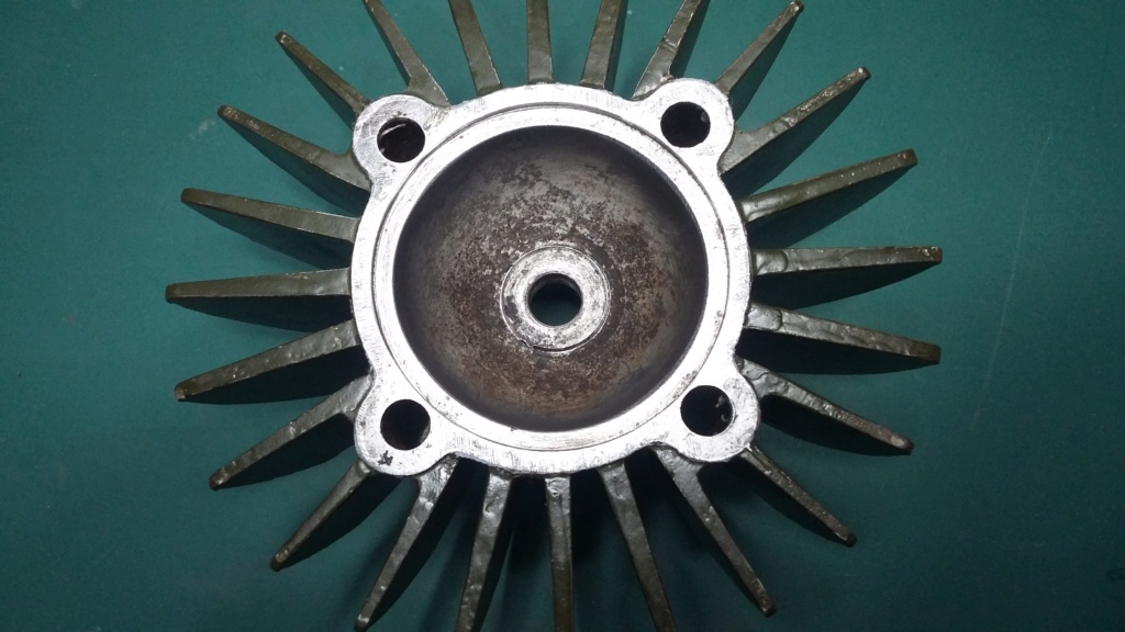
Inside of the cylinder head showing the gap, where the insert is leaking. (Between 4 and 6 o'clock)
Rather than try to repair the head at this time, I resorted to using a spare item, as this would allow the rebuild to proceed whilst still being able to attempt a repair on the old head later. Once the replacement head had been prepared and painted, I was ready to start the rebuild once again. Having determined that the reduction in head height was causing the issues with the piston hitting the head, I once again removed the second base gasket, leaving just the Klingersil one. With everything refitted I expectantly turned the engine over, only to find the gremlins had not finished with me yet. Although the engine was able to turn over for a full revolution, there was still a slight knocking sound at top dead centre. Although the replacement head had reduced the issue, the fact the piston was still slightly proud of the cylinder wall, meant the piston was able to just touch the head.

No gap around the thread on the spare head, nor is there a drilled hole in the top.
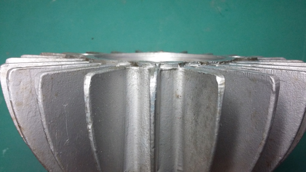
The replacement head showing a raised land of material on the mating surface.

Original head showing signs of having been skimmed.
The Klingersil gasket material I had used was only 1/64” thick, which was obviously not thick enough to prevent the issue from occurring. Unfortunately I didn’t have any other thicknesses available, so I had to order a pack of various thicknesses before I could proceed.
Once the sheet material had been received a new 1/16” base gasket was cut and fitted and for the umpteenth time the whole lot was reassembled. This time the engine was able to turn over without any further issues being encountered.
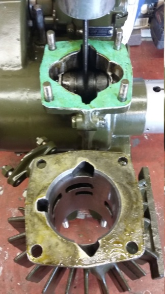
New 1/16" base gasket being made and fitted.

The piston edge is perfectly aligned with the top of the cylinder, once the new 1/16" gasket had been fitted.
I was now getting close to being in a position to see if I could coax some life out of the engine and get it to run, even if for a short burst. However before trying to run the engine, the magneto needed to be refitted but I decided to paint it first which was simply achieved.
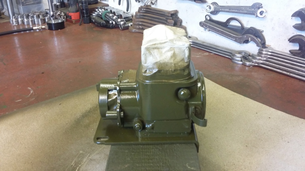
Main magneto body having paint applied.
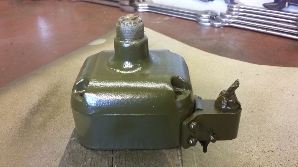
Magneto shielded top painted.
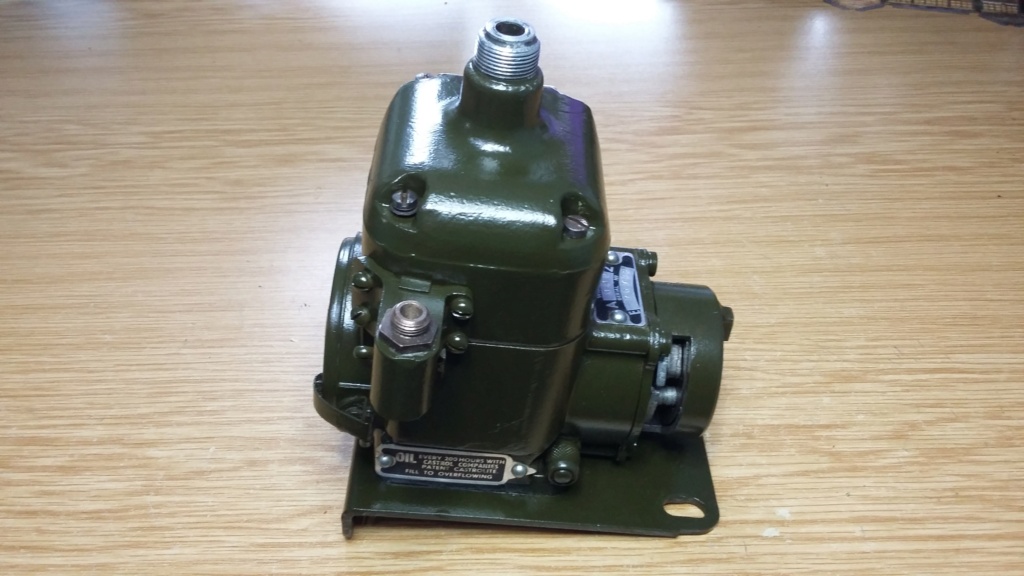
Completed magneto ready to be refitted, prior to possible engine test run.
At least I have had some success at last, hopefully with more successes to follow!
Neil.
Having ascertained a thicker base gasket seemed to resolve the issue, I had resigned myself to disassembling the engine once again. However before I got that far, I noticed that something wasn’t right with the cylinder head. When turning the engine over with the plug in, there were indications of compression leaking around the spark plug hole. On closer examination, there was an unexplained drilled hole around the edge of the threaded in plug insert, through which air could be seen to be escaping. Having removed the head to take a closer look it became apparent that not only was the head leaking around the insert but also the cylinder head had been heavily skimmed, which I believed was also causing the piston to clash with the head.

Unexplained drilling in the spark plug threaded insert. This allowed air to leak around the thread and out of the hole.

Inside of the cylinder head showing the gap, where the insert is leaking. (Between 4 and 6 o'clock)
Rather than try to repair the head at this time, I resorted to using a spare item, as this would allow the rebuild to proceed whilst still being able to attempt a repair on the old head later. Once the replacement head had been prepared and painted, I was ready to start the rebuild once again. Having determined that the reduction in head height was causing the issues with the piston hitting the head, I once again removed the second base gasket, leaving just the Klingersil one. With everything refitted I expectantly turned the engine over, only to find the gremlins had not finished with me yet. Although the engine was able to turn over for a full revolution, there was still a slight knocking sound at top dead centre. Although the replacement head had reduced the issue, the fact the piston was still slightly proud of the cylinder wall, meant the piston was able to just touch the head.

No gap around the thread on the spare head, nor is there a drilled hole in the top.

The replacement head showing a raised land of material on the mating surface.

Original head showing signs of having been skimmed.
The Klingersil gasket material I had used was only 1/64” thick, which was obviously not thick enough to prevent the issue from occurring. Unfortunately I didn’t have any other thicknesses available, so I had to order a pack of various thicknesses before I could proceed.
Once the sheet material had been received a new 1/16” base gasket was cut and fitted and for the umpteenth time the whole lot was reassembled. This time the engine was able to turn over without any further issues being encountered.

New 1/16" base gasket being made and fitted.

The piston edge is perfectly aligned with the top of the cylinder, once the new 1/16" gasket had been fitted.
I was now getting close to being in a position to see if I could coax some life out of the engine and get it to run, even if for a short burst. However before trying to run the engine, the magneto needed to be refitted but I decided to paint it first which was simply achieved.

Main magneto body having paint applied.

Magneto shielded top painted.

Completed magneto ready to be refitted, prior to possible engine test run.
At least I have had some success at last, hopefully with more successes to follow!
Neil.
neil (LE)- A credit to the forum

- Posts : 399
Join date : 2012-03-21
Age : 68
Location : N/W Kent
 Re: Scott Generating Set Restoration (Continues)
2 steps forward and 1 back! At least your still moving in the right direction - looking forward to the first run!
Alan
Alan
Alanengine- A credit to the forum

- Posts : 461
Join date : 2020-11-21
 Re: Scott Generating Set Restoration (Continues)
Small End Bush, Piston and Cylinder Rebuild. Pt. 3 (Success at last?)
With the magneto painted, it was refitted on the engine and the timing re-checked. This was achieved with the trip mechanism held back with gaffer tape, to allow for a static check to be made, using the markings on the flywheel. Originally this adjustment would have been made using one of the tools supplied with the sets, called a trammel. Basically a piece of bent rod which seems to have been held around the exhaust pipe, with the other end aligned with the markings on the crown of the flywheel. As I don’t possess an original trammel (if anyone has one, I would be interested to hear from them) to make the adjustment with, I fitted a length of tinned copper wire which was held under a magneto fixing bolt. This was then moved to point at the T.D.C. marking, once the engine was correctly set to T.D.C. With this fixed, the engine was turned backwards to the "Spark" marking and the points set to open in that position.

Trammel in position as per user instructions. Note marking is IGN 20
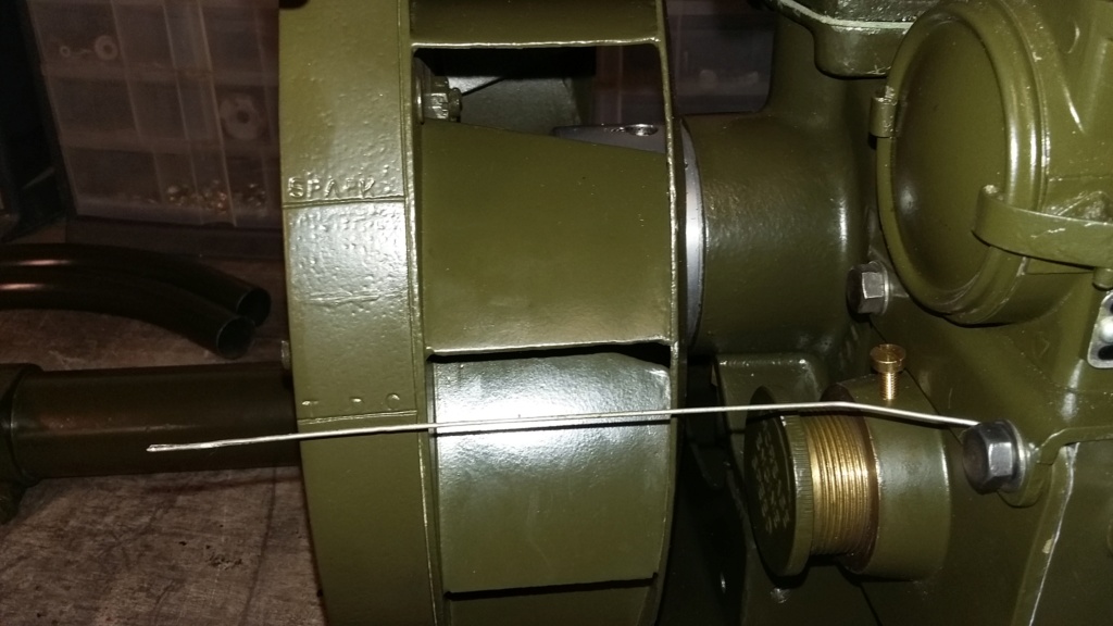
Tinned copper wire in use as a position indicator, in lieu of the trammel. Marking is now the word SPARK
In theory I was getting close to a position where a test of the engine was going to be possible. Initially I wasn’t able to fully run the engine, as the carburettor wasn’t fitted but I wanted to see if it would at least fire up. With a few drops of two stroke fuel added through the spark plug hole and some fed down into the crankcase the flywheel was turned over by hand, just enough to trip the magneto. After few attempts there was a rewarding couple of barks from the open exhaust, with the engine turning over for a couple of revolution. I called that a success, the first time this engine had ever fired up in my possession and quite possibly a very long time since it had ever fired.
This initial test was followed up by fitting the carburettor with the fuel pipe attached to allow fuel to be held in the float bowl without flooding out. I decided not to connect the governor at this time, as I didn’t want to risk the engine running away at full throttle. Instead I initially held the throttle open by hand, whilst turning the fly wheel over, to trip the magneto. This method was partially successful with the engine occasionally running for a few cycles but it was difficult to achieve a consistent result.
Next I fitted a piece of stiff wire to hold the throttle open and gave the carburettor a sniff of brake cleaner (I didn’t have any easy start to hand!). This was sufficient to help the engine to fire and to then take fuel from the carburettor to continue to run. Once running I was able to manually operate the throttle to control the engine speed and to see the disconnected governor controls move with the engine revs. The engine continued to run for 20 - 30 seconds, to me that was a successful first run of the engine, unfortunately not captured on video.
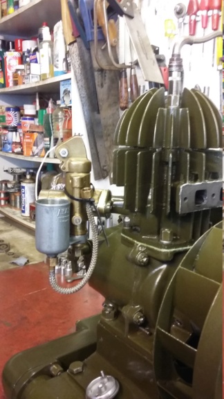
Carburettor fitted with the fuel pipe attached to allow fuel bowl to be filled and the stiff white wire holding the throttle open.
Next I want to be able to mount the engine onto the sub-chassis, with all the cowling fitted, to the point of completion. I believe, with the flywheel removed, it should be possible to move the unit around with the assistance of one other person. Any further than this would make it impossible to move without it becoming dangerous!
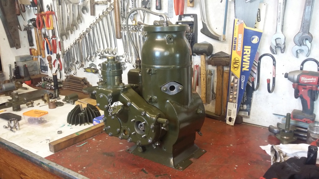
Test fitting of the cowling, prior to final assembly.

Engine unit, minus flywheel, mounted on sub-chassis. The rest of the engine will be built up in situ, hopefully remaining safely manageable.
I hope to undertake some more test runs of the engine but I will need to find another way to turn the engine over for starting. Once the exhaust pipes are fitted it is not possible to turn the flywheel over without seriously risking trapping your fingers between the flywheel and the exhaust system. Ask me how I know! That was just slowly turning the engine over compression to align the ignition marker, if I had been sharply pulling the engine over it would have really hurt.
Hopefully more to come soon but I am still challenged about how far I can proceed until I can build the complete unit up on a suitable trailer.
Neil.
With the magneto painted, it was refitted on the engine and the timing re-checked. This was achieved with the trip mechanism held back with gaffer tape, to allow for a static check to be made, using the markings on the flywheel. Originally this adjustment would have been made using one of the tools supplied with the sets, called a trammel. Basically a piece of bent rod which seems to have been held around the exhaust pipe, with the other end aligned with the markings on the crown of the flywheel. As I don’t possess an original trammel (if anyone has one, I would be interested to hear from them) to make the adjustment with, I fitted a length of tinned copper wire which was held under a magneto fixing bolt. This was then moved to point at the T.D.C. marking, once the engine was correctly set to T.D.C. With this fixed, the engine was turned backwards to the "Spark" marking and the points set to open in that position.

Trammel in position as per user instructions. Note marking is IGN 20

Tinned copper wire in use as a position indicator, in lieu of the trammel. Marking is now the word SPARK
In theory I was getting close to a position where a test of the engine was going to be possible. Initially I wasn’t able to fully run the engine, as the carburettor wasn’t fitted but I wanted to see if it would at least fire up. With a few drops of two stroke fuel added through the spark plug hole and some fed down into the crankcase the flywheel was turned over by hand, just enough to trip the magneto. After few attempts there was a rewarding couple of barks from the open exhaust, with the engine turning over for a couple of revolution. I called that a success, the first time this engine had ever fired up in my possession and quite possibly a very long time since it had ever fired.
This initial test was followed up by fitting the carburettor with the fuel pipe attached to allow fuel to be held in the float bowl without flooding out. I decided not to connect the governor at this time, as I didn’t want to risk the engine running away at full throttle. Instead I initially held the throttle open by hand, whilst turning the fly wheel over, to trip the magneto. This method was partially successful with the engine occasionally running for a few cycles but it was difficult to achieve a consistent result.
Next I fitted a piece of stiff wire to hold the throttle open and gave the carburettor a sniff of brake cleaner (I didn’t have any easy start to hand!). This was sufficient to help the engine to fire and to then take fuel from the carburettor to continue to run. Once running I was able to manually operate the throttle to control the engine speed and to see the disconnected governor controls move with the engine revs. The engine continued to run for 20 - 30 seconds, to me that was a successful first run of the engine, unfortunately not captured on video.

Carburettor fitted with the fuel pipe attached to allow fuel bowl to be filled and the stiff white wire holding the throttle open.
Next I want to be able to mount the engine onto the sub-chassis, with all the cowling fitted, to the point of completion. I believe, with the flywheel removed, it should be possible to move the unit around with the assistance of one other person. Any further than this would make it impossible to move without it becoming dangerous!

Test fitting of the cowling, prior to final assembly.

Engine unit, minus flywheel, mounted on sub-chassis. The rest of the engine will be built up in situ, hopefully remaining safely manageable.
I hope to undertake some more test runs of the engine but I will need to find another way to turn the engine over for starting. Once the exhaust pipes are fitted it is not possible to turn the flywheel over without seriously risking trapping your fingers between the flywheel and the exhaust system. Ask me how I know! That was just slowly turning the engine over compression to align the ignition marker, if I had been sharply pulling the engine over it would have really hurt.
Hopefully more to come soon but I am still challenged about how far I can proceed until I can build the complete unit up on a suitable trailer.
Neil.
neil (LE)- A credit to the forum

- Posts : 399
Join date : 2012-03-21
Age : 68
Location : N/W Kent
 Re: Scott Generating Set Restoration (Continues)
What wrong with an every day common starting handle.
Maryalice
Maryalice
maryalice- Life Member

- Posts : 1310
Join date : 2010-01-23
Age : 70
Location : Bedfordshire
 Re: Scott Generating Set Restoration (Continues)
Maryalice, unfortunately there isn't any facility to directly use a starting handle on these engines. In normal use the starting handle is remote from the engine being linked by chain from the control desk starter chain wheel. On the engine there is only a short shaft which is pressed in by foot, to engage the ratchet, whilst the remote handle is turned. I believe some owners have adapted the short shaft to accept a clamped on handle but even then it is difficult, as there is not much available space to allow for a reasonable length of handle swing.
Neil.
Neil.
neil (LE)- A credit to the forum

- Posts : 399
Join date : 2012-03-21
Age : 68
Location : N/W Kent
 Re: Scott Generating Set Restoration (Continues)
Mine was adapted for a Petter A handle, worked find for the flick over compression when it was playing ball.... there is a reason there isn't a start up video...
Used a gert big nut with a groove ground into it.
Used a gert big nut with a groove ground into it.
StuartTurnerSteve- Life Member

- Posts : 534
Join date : 2020-01-02
 Re: Scott Generating Set Restoration (Continues)
Steve, I know what you mean, these engines have a reputation for being difficult to start. This seems perverse when you think what their function was and the need to get them up and running in the shortest possible time, to be able to engage the enemy aircraft.
I know the use of any form of starting fluid is frowned upon but I think if it means the engine will start easily and reliably, then I might be tempted to use a squirt through the carburettor just to aid the starting process. Up until now when starting my Jowett generator set, I have had to use a priming shot of fuel through the sparking plug hole to achieve any form of reasonable starting. However this is a long winded process involving accessing the plug, removing it and then attempting to add fuel through the plug hole which is below the level of the canopy top making it difficult to achieve, without either spilling fuel or over fuelling. If this action fails to start the engine, the whole process has to be repeated. This can be frustrating especially when the public are watching and making wry comments, such as " Don't worry they will have flown back to their base before you get that started".
I have undertaken some basic research on the Amal TT carburettor, as fitted to these units and it seems as though they may not have been totally suitable for this use. Being primarily designed as a sporting/racing motorcycle carburettor, easy starting isn't the primary objective. Recalcitrant bikes can be encouraged to perform by kicking them over briskly or push starting, neither of these options are available to the operators of the generating sets, who's only option was to pull them over just once to operate the flick magneto which didn't allow much fuel to be drawn into the cylinder.
I imagine when the engines were new and the compression was at its best, then the starting may have been easier. Now they are older and more worn, I assume the compression is lower, causing a less reliable start. I would be interested to hear what anyone else would think about resorting to starting aids, such as easy-start sprays.
Today I've managed to continue with the final assembly of the engine unit, fitting the flywheel bearing, its outer cover and inner fan cone. Most of these items are fitted with bolts with drilled heads for locking wire to be threaded through to prevent them coming loose. I've used tinned copper wire to retain this feature.
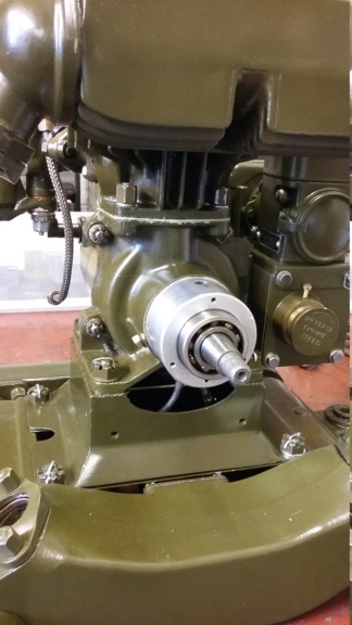
Flywheel bearing being fitted.
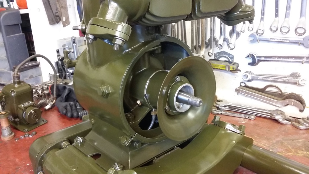
Locking wire used on the flywheel bearing cover and the fan cone, as originally fitted.
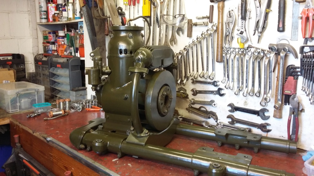
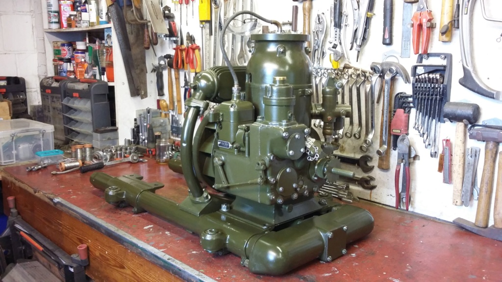
The nearly completed engine unit, attached to the sub-chassis. Flywheel will be removed before attempting to lift or move the assembly about.
A new addition joins the collection!
Last week I was lucky enough to add another Jowett badged PA engine to my collection. Although this one isn't in the best condition, with the Amal carburettor missing, having a Villiers one instead, the cylinder cowl being made from tin rather than the cast aluminium original and the front exhaust chamber being a fabrication, it was still worth acquiring. On the positive side it does still retain the full exhaust system and the engine does supposedly run, although I have not tried it, as I rather ensure there isn't anything mechanically wrong with it before running it. I'm not certain if I'm going to restore this one or keep it for spares to keep the others going, that will depend on how all the other projects go.
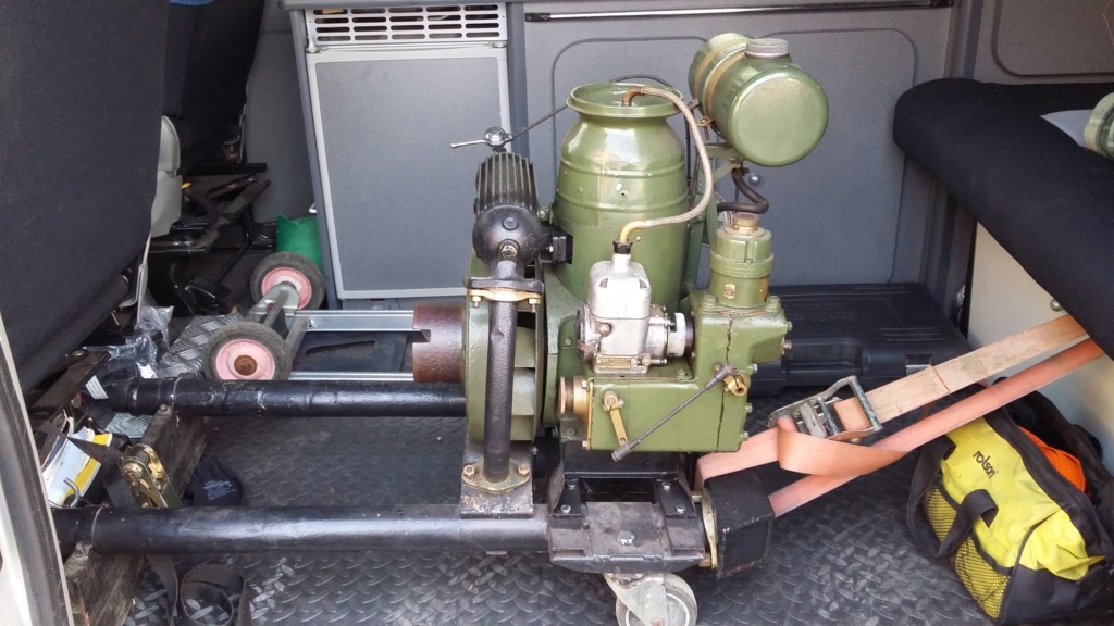
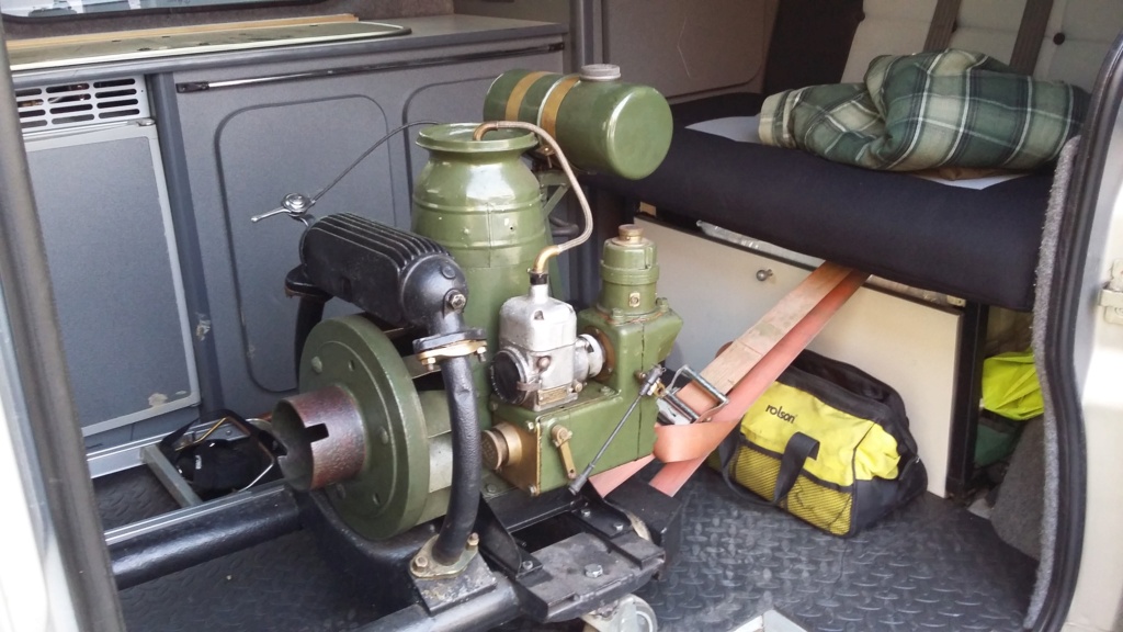
New engine loaded in the van. The replacement tin cowl is seen, this must have been quite difficult to make. It also has a non-original rope start attachment fitted.

Engine had to be removed from the exhaust sub-assembly to be able to lift it into the workshop. Note the fabricated exhaust header.

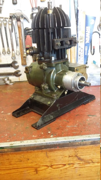
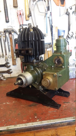
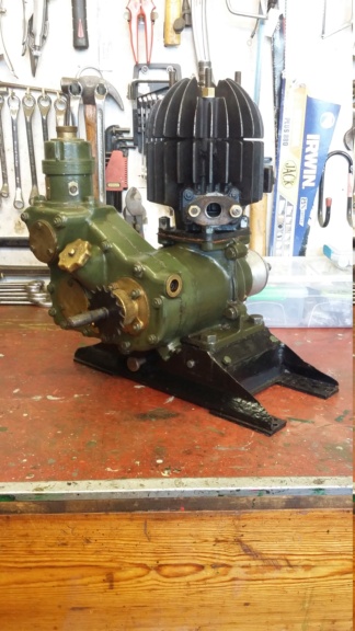
On the bench for an initial examination.
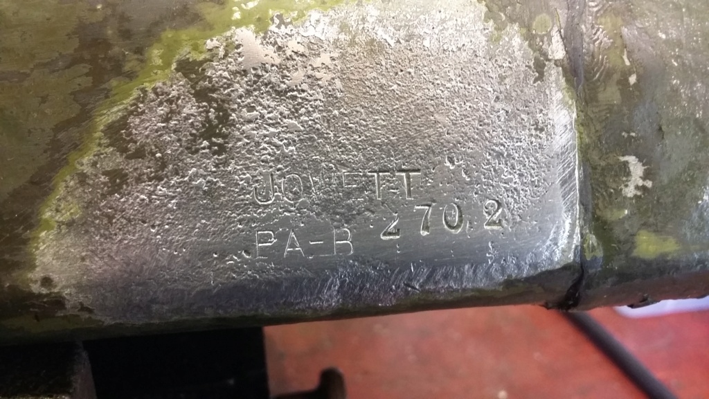
Serial number revealed, Jowett PA-B 2702
I know the use of any form of starting fluid is frowned upon but I think if it means the engine will start easily and reliably, then I might be tempted to use a squirt through the carburettor just to aid the starting process. Up until now when starting my Jowett generator set, I have had to use a priming shot of fuel through the sparking plug hole to achieve any form of reasonable starting. However this is a long winded process involving accessing the plug, removing it and then attempting to add fuel through the plug hole which is below the level of the canopy top making it difficult to achieve, without either spilling fuel or over fuelling. If this action fails to start the engine, the whole process has to be repeated. This can be frustrating especially when the public are watching and making wry comments, such as " Don't worry they will have flown back to their base before you get that started".
I have undertaken some basic research on the Amal TT carburettor, as fitted to these units and it seems as though they may not have been totally suitable for this use. Being primarily designed as a sporting/racing motorcycle carburettor, easy starting isn't the primary objective. Recalcitrant bikes can be encouraged to perform by kicking them over briskly or push starting, neither of these options are available to the operators of the generating sets, who's only option was to pull them over just once to operate the flick magneto which didn't allow much fuel to be drawn into the cylinder.
I imagine when the engines were new and the compression was at its best, then the starting may have been easier. Now they are older and more worn, I assume the compression is lower, causing a less reliable start. I would be interested to hear what anyone else would think about resorting to starting aids, such as easy-start sprays.
Today I've managed to continue with the final assembly of the engine unit, fitting the flywheel bearing, its outer cover and inner fan cone. Most of these items are fitted with bolts with drilled heads for locking wire to be threaded through to prevent them coming loose. I've used tinned copper wire to retain this feature.

Flywheel bearing being fitted.

Locking wire used on the flywheel bearing cover and the fan cone, as originally fitted.


The nearly completed engine unit, attached to the sub-chassis. Flywheel will be removed before attempting to lift or move the assembly about.
A new addition joins the collection!
Last week I was lucky enough to add another Jowett badged PA engine to my collection. Although this one isn't in the best condition, with the Amal carburettor missing, having a Villiers one instead, the cylinder cowl being made from tin rather than the cast aluminium original and the front exhaust chamber being a fabrication, it was still worth acquiring. On the positive side it does still retain the full exhaust system and the engine does supposedly run, although I have not tried it, as I rather ensure there isn't anything mechanically wrong with it before running it. I'm not certain if I'm going to restore this one or keep it for spares to keep the others going, that will depend on how all the other projects go.


New engine loaded in the van. The replacement tin cowl is seen, this must have been quite difficult to make. It also has a non-original rope start attachment fitted.

Engine had to be removed from the exhaust sub-assembly to be able to lift it into the workshop. Note the fabricated exhaust header.


On the bench for an initial examination.

Serial number revealed, Jowett PA-B 2702
neil (LE)- A credit to the forum

- Posts : 399
Join date : 2012-03-21
Age : 68
Location : N/W Kent
 Re: Scott Generating Set Restoration (Continues)
Very nice, Jowett seemed to have made the lions share, mine was also a Jowett made one.
I'd have another in a heart beat, such odd things... only sold mine as the guy wanted it to go on a Bofors set they were restoring in a bunker out The Lizard.
I'd have another in a heart beat, such odd things... only sold mine as the guy wanted it to go on a Bofors set they were restoring in a bunker out The Lizard.
StuartTurnerSteve- Life Member

- Posts : 534
Join date : 2020-01-02
 Re: Scott Generating Set Restoration (Continues)
Have you thought of adding a Ki-Gass system to it?, would make a nice period addition as they were quite popular in the 40's.
_________________
Stuart

Robotstar5- Life Member

- Posts : 1109
Join date : 2018-09-25
 Re: Scott Generating Set Restoration (Continues)
Well I must admit I had to do some research on what a Ki-Gass system is, having never come across this reference before. Although I do not understand exactly how it could be retro fitted to a Scott/Jowett engine, it does never the less look to be quite an interesting and potentially useful device. Further investigations may be necessary before any decisions as to a way forward could be made, although what I have discovered in my initial searches is that replacement / remanufactured parts seem to be very expensive, possibly because of their use in high end vehicles and the aviation industry.
Any ideas as to how one of these devices could be adapted and fitted to the engine, as well as where the essential components may be sourced, at a cost that is less than the engine's value would be welcome. If it is proven to be an engineering and a financial feasibility, then I might be tempted to try one of these on a stand alone engine, to test the concept.
Thank you for your suggestion.
Neil.
neil (LE)- A credit to the forum

- Posts : 399
Join date : 2012-03-21
Age : 68
Location : N/W Kent
Page 9 of 13 •  1, 2, 3 ... 8, 9, 10, 11, 12, 13
 Similar topics
» Scott PAB Restoration
» Kubota diesel KND3
» Trolley for Villiers Mk15 wooden toolbox new pics 5-9-2016
» Petter generating set - might turn into a project
» Douglas FT35 generating set
» Kubota diesel KND3
» Trolley for Villiers Mk15 wooden toolbox new pics 5-9-2016
» Petter generating set - might turn into a project
» Douglas FT35 generating set
Page 9 of 13
Permissions in this forum:
You cannot reply to topics in this forum