Lister H4 Pump Disassembly
+8
chrismac
neil (LE)
Foden
Robotstar5
oldgit
tony RA
68jcb
matthew92
12 posters
Page 3 of 6
Page 3 of 6 •  1, 2, 3, 4, 5, 6
 Re: Lister H4 Pump Disassembly
As you say, you can always make a U shaped one to fit over the shaft to save you taking the pulley off. I've just checked and the two guards are both the same on my H2, so the pulley has to come off to fit or remove the guard on that side.
As with most vintage machines with a production period of 10s of years, the design of certain parts tended to change over time, either to do the job better or to reduce manufacturing costs, so differences in the design of some parts are almost inevitable.
As with most vintage machines with a production period of 10s of years, the design of certain parts tended to change over time, either to do the job better or to reduce manufacturing costs, so differences in the design of some parts are almost inevitable.
_________________
Jules.

A Lister- A true Stationary engine owner

- Posts : 166
Join date : 2013-01-04
Location : South Cheshire
 Re: Lister H4 Pump Disassembly
Hi all, just a short update, on what was meant to be a quick and simple job of painting the trolley and wheels. Somehow it took all day, started this morning on the wheels, to give the undercoat on the frame as long as possible to be properly dry, as it states 24 hours between coats. Then this afternoon I applied the first top coat on the frame, looking at it, it will require a rub down and a second coat. I'll probably leave doing that for a couple of days or so, as I've found you need longer than 24 hours between coats, if you're going to rub down before applying the second coat. Whilst I'm waiting "for paint to dry" I will sort out some orders for the remaining items required to finish the project. I need the pump valve rubbers, some JB Weld or equivalent, if I'm going to attempt a repair on the output flange, as I mentioned previously. Any comments on the suitability of this type of compound, to repair this item would be helpful. I will also order some parts for the Lister D, including a magneto chain, a set of gaskets and some transfers to finish it off. If you're using this time, to work on any of your projects, I hope you are enjoying the opportunity to undertake the work and hope it relieves the impact of lock down and self isolation, Neil.
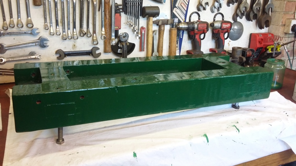
First top coat applied. A second coat will be required, once this paint is hard enough to be gently rubbed down.
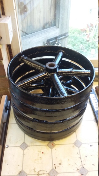
The trolley wheels stacked up, having been given a coat of Hammerite smooth.

First top coat applied. A second coat will be required, once this paint is hard enough to be gently rubbed down.

The trolley wheels stacked up, having been given a coat of Hammerite smooth.
neil (LE)- A credit to the forum

- Posts : 399
Join date : 2012-03-21
Age : 68
Location : N/W Kent
 Re: Lister H4 Pump Disassembly
Yep that's it, can't remember quite how it was done, if I can get a picture of it I will.

matthew92- Born to be wild

- Posts : 25
Join date : 2019-09-30
 Re: Lister H4 Pump Disassembly
Matthew92, thank you for confirming my thoughts on the guards, hopefully I'll be able to sort something out, once everything is back to normal.
Whilst I am waiting for the paint to fully dry on the trolley, before rubbing it down, I spent today dealing with an issue that was highlighted during the H4 pump renovations. In some ways I should really start a new thread, as although this is linked to something identified during the pump restoration, it is strictly nothing to do with the pump or Lister D renovations. However it does involves an engine driven piece of equipment, so at least I'm in the correct area of the forum.
For those of you who have followed this thread, you might remember I had an issue with the stability of the H4 pump on its trolley, after I had fitted some temporary swivel wheels. As these wheels had to be fitted slightly inboard of the trolley and due to the top heavy nature of the pump, this resulted in the pump having a very high centre of gravity. This nearly ended in disaster, when the complete set, uncontrollably rolled over.
Having luckily survived this near miss with the pump, I became very concerned about a similar set up on my Jowett (Scott) Generating set. I really felt I needed to learn from this potentially serious issue and not to risk a similar event, which could end up at best damaging the generating set, or worse injuring someone.
I convinced myself that I needed to do something about it straight away, before even attempting to move the set off the trailer. I had lost all confidence that it would not fall over on the way down the ramps, due to the uneven nature of the ground.
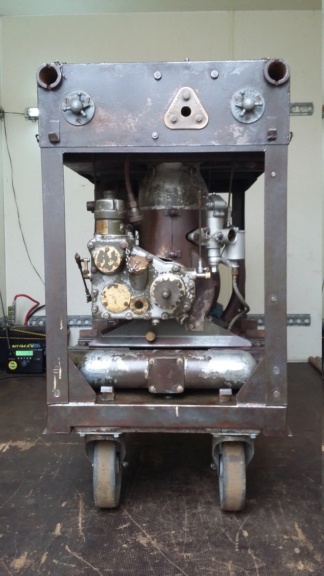
Trolley wheels as fitted to the Jowett generating set. Showing the inboard nature of the set up, resulting in a high centre of gravity, causing potentially dangerous instability.
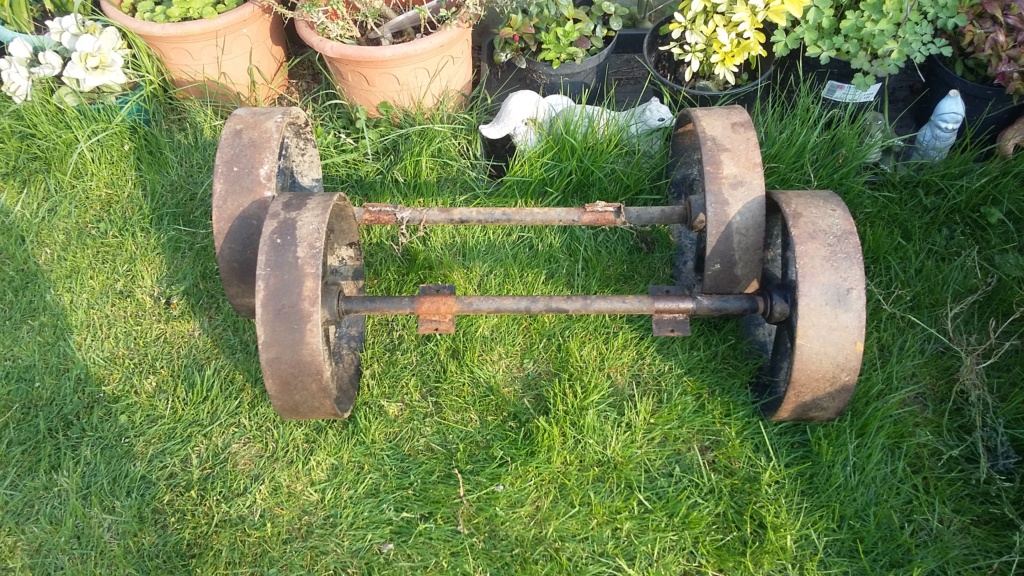
The wheel set which became available from the dismantled H4 pump and Lister D trolley. Very fortunately, just wide enough to fit the generator set.

The lower section of the generator set lowered down the ramp quite safely. It became unstable once the top had been fitted.
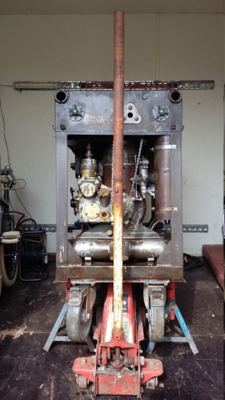
Generator being jacked up to remove trolley wheels.
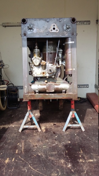
Two wheels on my wagon!
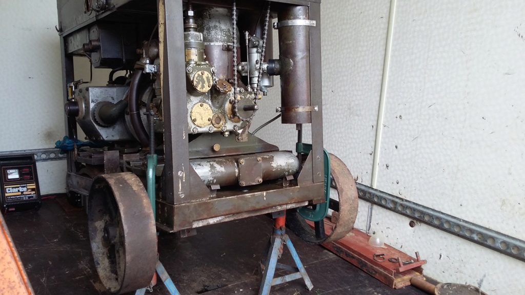
Trial fit of the replacement wheel set, just wide enough, there's lucky!
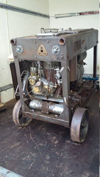
New front wheel set fitted. Looking much better and hopefully far more stable. Rear set to follow.
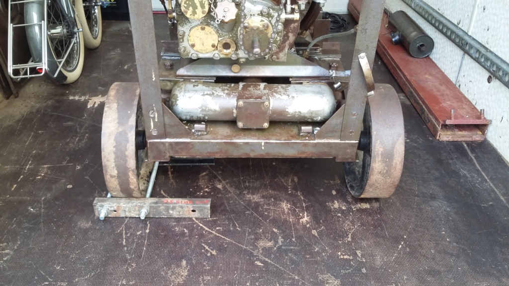
Wheel clamp fitted to lock the wheels, in lieu of the locking trolley wheels.
Whilst I am waiting for the paint to fully dry on the trolley, before rubbing it down, I spent today dealing with an issue that was highlighted during the H4 pump renovations. In some ways I should really start a new thread, as although this is linked to something identified during the pump restoration, it is strictly nothing to do with the pump or Lister D renovations. However it does involves an engine driven piece of equipment, so at least I'm in the correct area of the forum.
For those of you who have followed this thread, you might remember I had an issue with the stability of the H4 pump on its trolley, after I had fitted some temporary swivel wheels. As these wheels had to be fitted slightly inboard of the trolley and due to the top heavy nature of the pump, this resulted in the pump having a very high centre of gravity. This nearly ended in disaster, when the complete set, uncontrollably rolled over.
Having luckily survived this near miss with the pump, I became very concerned about a similar set up on my Jowett (Scott) Generating set. I really felt I needed to learn from this potentially serious issue and not to risk a similar event, which could end up at best damaging the generating set, or worse injuring someone.
I convinced myself that I needed to do something about it straight away, before even attempting to move the set off the trailer. I had lost all confidence that it would not fall over on the way down the ramps, due to the uneven nature of the ground.

Trolley wheels as fitted to the Jowett generating set. Showing the inboard nature of the set up, resulting in a high centre of gravity, causing potentially dangerous instability.

The wheel set which became available from the dismantled H4 pump and Lister D trolley. Very fortunately, just wide enough to fit the generator set.

The lower section of the generator set lowered down the ramp quite safely. It became unstable once the top had been fitted.

Generator being jacked up to remove trolley wheels.

Two wheels on my wagon!

Trial fit of the replacement wheel set, just wide enough, there's lucky!

New front wheel set fitted. Looking much better and hopefully far more stable. Rear set to follow.

Wheel clamp fitted to lock the wheels, in lieu of the locking trolley wheels.
neil (LE)- A credit to the forum

- Posts : 399
Join date : 2012-03-21
Age : 68
Location : N/W Kent
 Re: Lister H4 Pump Disassembly
Niel you/r bigger gland packing left here today about 3-30
tony RA- A credit to the forum

- Posts : 279
Join date : 2013-11-16
Age : 77
Location : newtown powys
 Re: Lister H4 Pump Disassembly
Tony, many thanks for that. The first package has literally just been delivered, just in time to let you know. Based on that timescale, I don't expect your latest one to arrive for a few days yet, I'll be in contact as soon as it does. In the meantime, I will look over the instruction you kindly sent with the first pack, to make sure I know how to fit it correctly. Thanks again, Neil.
neil (LE)- A credit to the forum

- Posts : 399
Join date : 2012-03-21
Age : 68
Location : N/W Kent
 Re: Lister H4 Pump Disassembly
Hi, today I'm back working on the H4 pump trolley. The first coat of paint has had a couple of days to harden off, so I decided to give it a gentle rub down, to see if it was ready. It seemed alright, although I find you can never leave it long enough, even so I carried on rubbing it down. However as the weather around here has changed dramatically, from being ideal painting conditions, to being anything but perfect, having turned cold and damp, I didn't want to apply the top coat of paint in the garage, in those conditions. To overcome this issue, I decamped into the house to continue with the painting. This could have been dangerous for me, as my wife might have thought that if he can wield a paint brush around indoors on his hobby, then he could also do some decorating. So far I seemed to have got away with it, hopefully she will forget about it before too long, otherwise I will never finish the engines and other things I'm working on. I will now have to wait at least a week, for the paint to harden off sufficiently, before I attempt to rebuild the pump onto the trolley. I always seem to damage new paint when putting things back together. Hopefully I've got enough to keep me occupied, so I don't get tempted to do it too soon, while the paint is still soft. Hope you are all keeping happily busy and well, Neil.
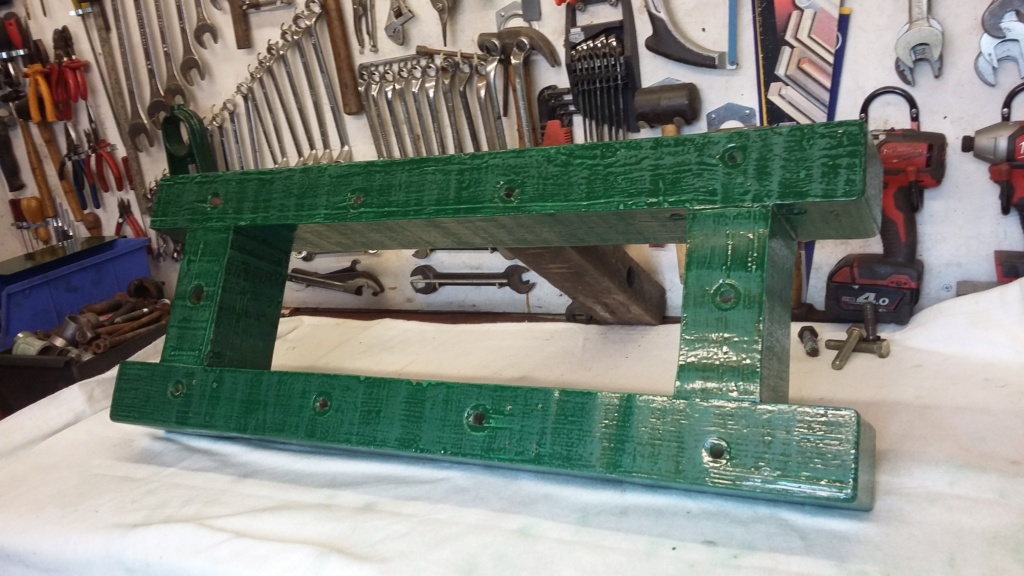
Frame being rubbed down in the garage.
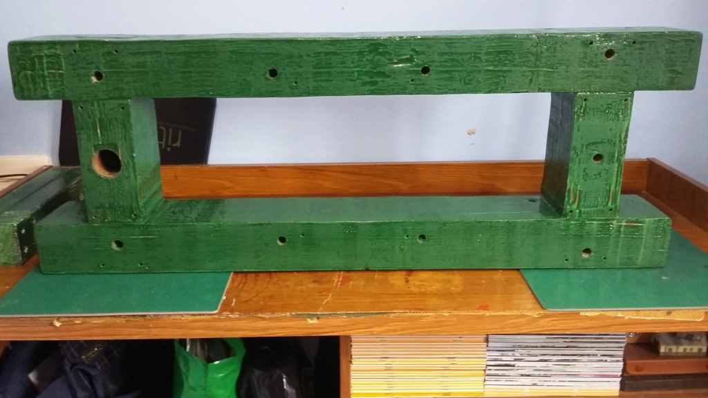
Transferred indoors, without domestic knowledge!
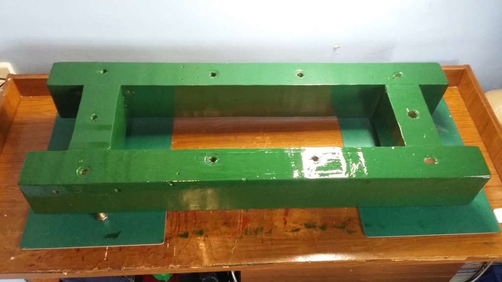
A slightly hazy picture of the finished paintwork. Hopefully it looks better in real life.

Frame being rubbed down in the garage.

Transferred indoors, without domestic knowledge!

A slightly hazy picture of the finished paintwork. Hopefully it looks better in real life.
neil (LE)- A credit to the forum

- Posts : 399
Join date : 2012-03-21
Age : 68
Location : N/W Kent
 Re: Lister H4 Pump Disassembly
Hi Tony, just to let you know your package has arrived, thank you very much. I will give you a call, if you let me know when it would be convenient. Kind regards, Neil.
neil (LE)- A credit to the forum

- Posts : 399
Join date : 2012-03-21
Age : 68
Location : N/W Kent
 Re: Lister H4 Pump Disassembly
Hi Neil
Glad you got it It was posted on the 27th hope this will get you fixed up I/m mostly near the phone most evenings every day
Glad you got it It was posted on the 27th hope this will get you fixed up I/m mostly near the phone most evenings every day
tony RA- A credit to the forum

- Posts : 279
Join date : 2013-11-16
Age : 77
Location : newtown powys
 Lister H4 Pump Disassembly and Jowett Generator Set.
Hi, I've not progressed the pump much since last week, as I wanted to let the paint on the trolley harden off a little, before I attempted to reassemble anything. That doesn't mean I've not been doing anything. Whilst waiting for "paint to dry" I have continued to fit the trolley wheels to the Jowett (Scott) generator set. Due to not being able to get out and buy materials, I have had to "make do and mend" as they used to say. This has meant that I have had to make wood up to the required thickness, by laminating pieces together to achieved the necessary dimensions. Whilst I had the unit on the stands to fit the wheels, I took the opportunity to apply some rust protection on the underside, using spray underseal. The generator set is now on the new set of wheels, although further work is required to complete but if it is necessary, I can now more safely lower the set off the trailer.
Having got to a point where I am happy that the generator is safely mobile again, I have just started to put the Lister pump back together on its trolley. Hopefully I will be able to complete this over the next week, especially as I now have some suitable gland packing material, thank you Tony. Then I can get back to repainting the Lister D, with the intention of being able to belt the two up together again, for the first time in many years.
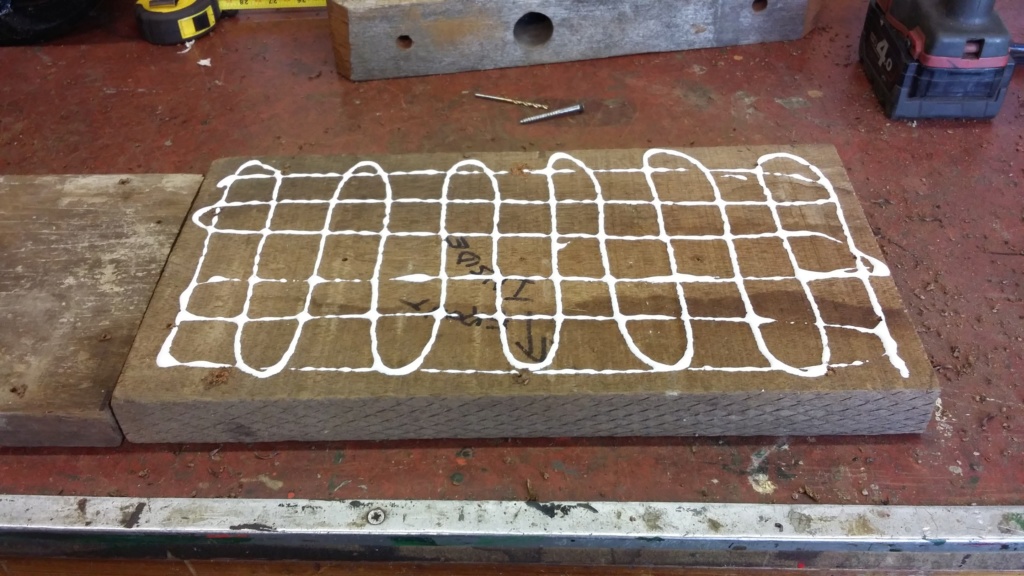
Making up the laminated wooden block
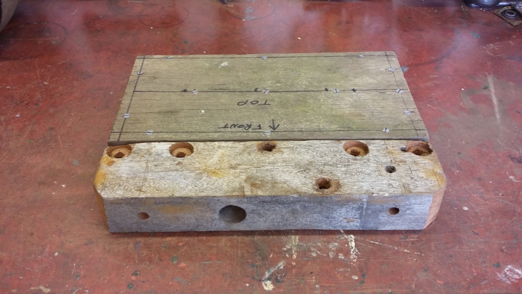
Finished block made up and screwed together to match the thickness required, shown against the sample piece.
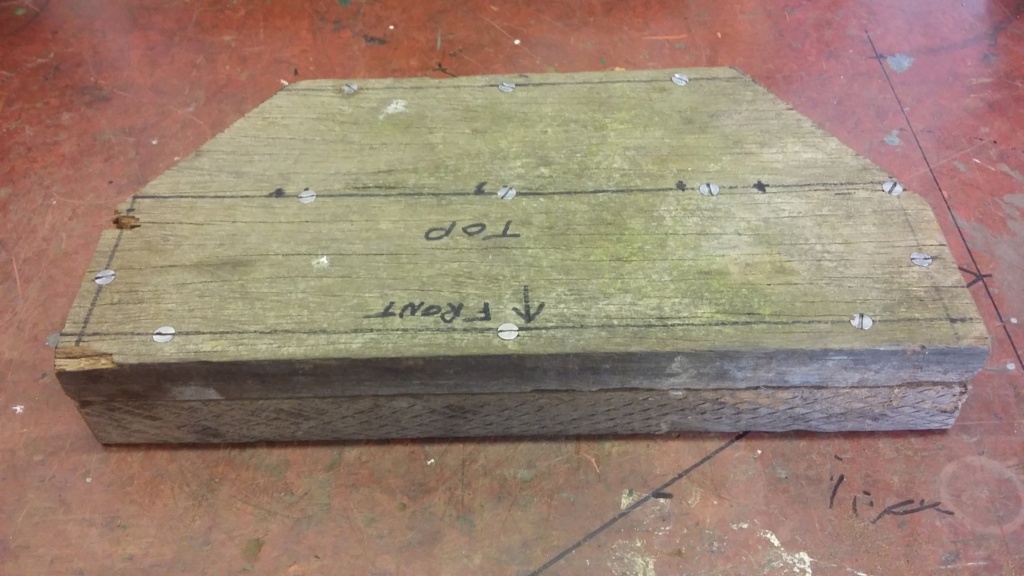
Block cut to shape to mount the axle on and to fit under the frame.
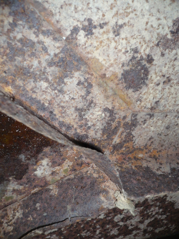
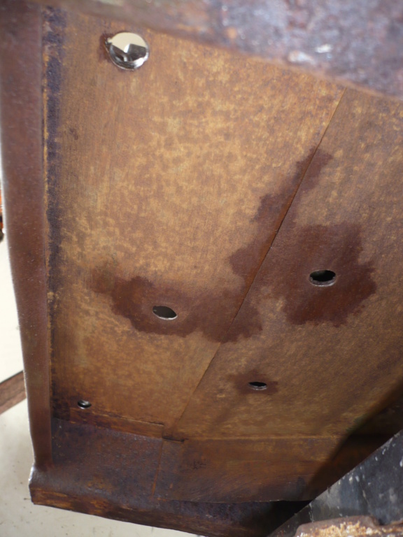
General state of the underside before being cleaned up.
Surface rubbed down ready for the coating to be applied.
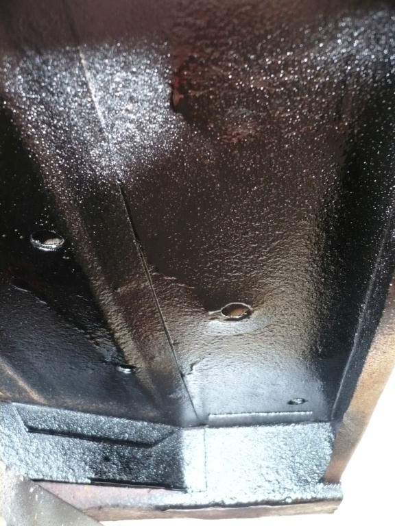
Underseal applied.
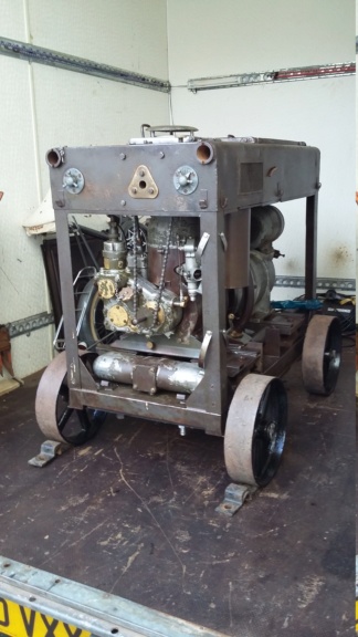
Generator set with the new wheels fitted.
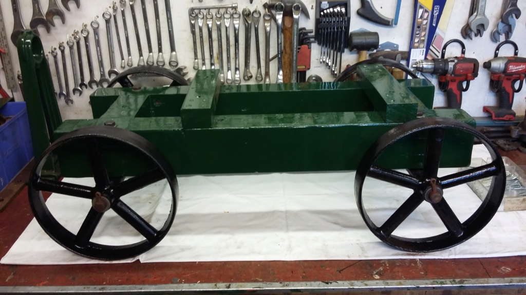
Pump trolley being rebuilt.
Having got to a point where I am happy that the generator is safely mobile again, I have just started to put the Lister pump back together on its trolley. Hopefully I will be able to complete this over the next week, especially as I now have some suitable gland packing material, thank you Tony. Then I can get back to repainting the Lister D, with the intention of being able to belt the two up together again, for the first time in many years.

Making up the laminated wooden block

Finished block made up and screwed together to match the thickness required, shown against the sample piece.

Block cut to shape to mount the axle on and to fit under the frame.

General state of the underside before being cleaned up.

Surface rubbed down ready for the coating to be applied.

Underseal applied.

Generator set with the new wheels fitted.

Pump trolley being rebuilt.
neil (LE)- A credit to the forum

- Posts : 399
Join date : 2012-03-21
Age : 68
Location : N/W Kent
 Re: Lister H4 Pump Disassembly
Having now finished the urgent work required to make the Jowett generator set safe to move, I am now back working on the Lister H4 pump. The last time, I had just started to rebuild the pump trolley, ready to mount the pump onto it. This was achieved but only loosely assembled, to enable further work to be undertaken. This proved to be the correct decision, as I was soon to take it all apart again.
This is where I have to admit that I had not fully understood how the gland packing material is fitted. I initially thought that I was just replacing the pieces that had come away with the gland plates, I hadn't realised that the spindle bore was recessed, forming what I now believe is called a stuffing box! On closer inspection I could see the old gland packing was still inside the pump and needed to be extracted. Fortunately I have been supplied with new packing material, instructions and an extraction tool. Armed with the knowledge of what was required, I extracted the old packing and cleaned up the housing, ready for the replacement to be fitted. I have also cut two of the four new packing rings ready to be installed but I'm slightly nervous about actually fitting them. Instructions suggest the use of a split sleeve to insert the packing, not having one of these I will have to improvise but that will have to wait for another day. Tomorrow our road is having a socially separated V.E. Day street party in our front gardens, with appropriate music, food, drinks and I hope to exhibit the WW2 Jowett generator set and my 1919 "Victory" Model M Petter, neighbours willing!
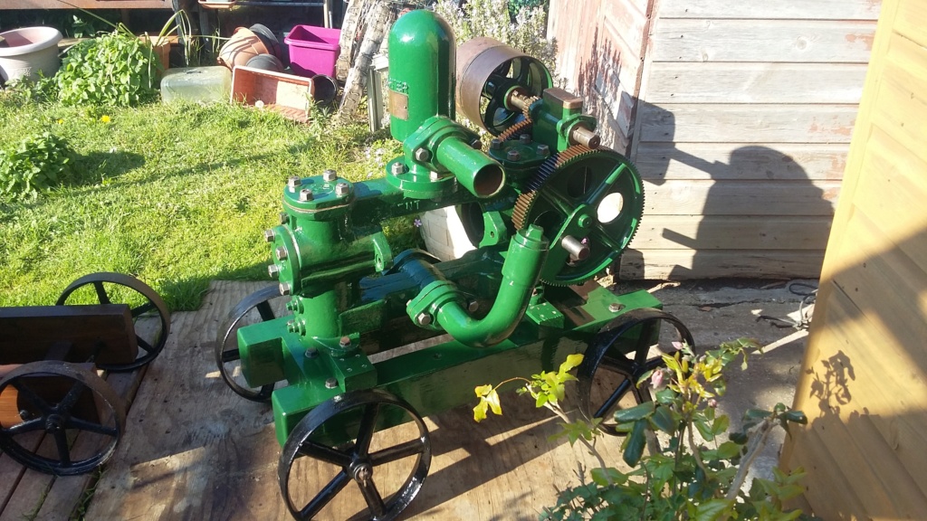
Pump reunited with the repainted trolley.
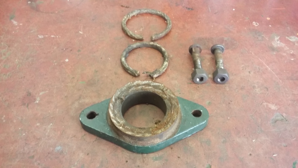
This is what I thought the packing consisted of.
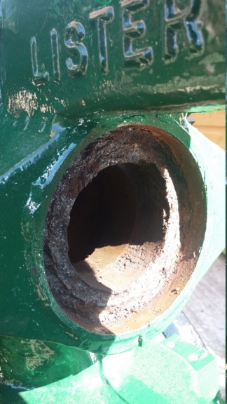
Closer inspection shows the packing is recessed into a stuffing box. I thought the inner edge was part of the casting.
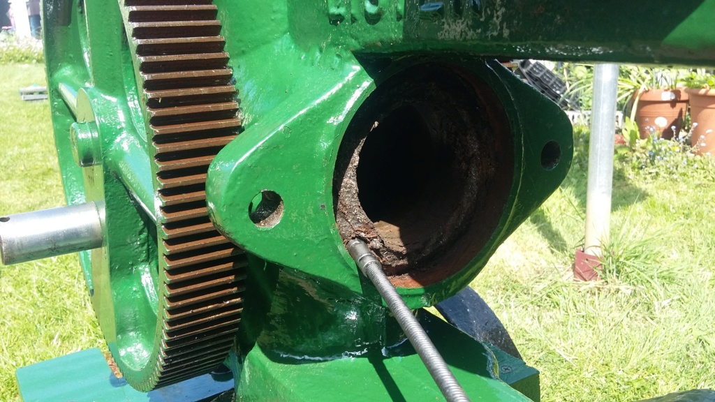
Extraction tool in use.
!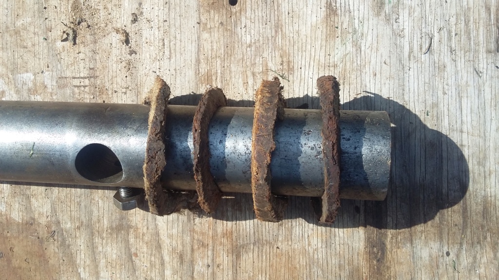
Old packing removed from casting.
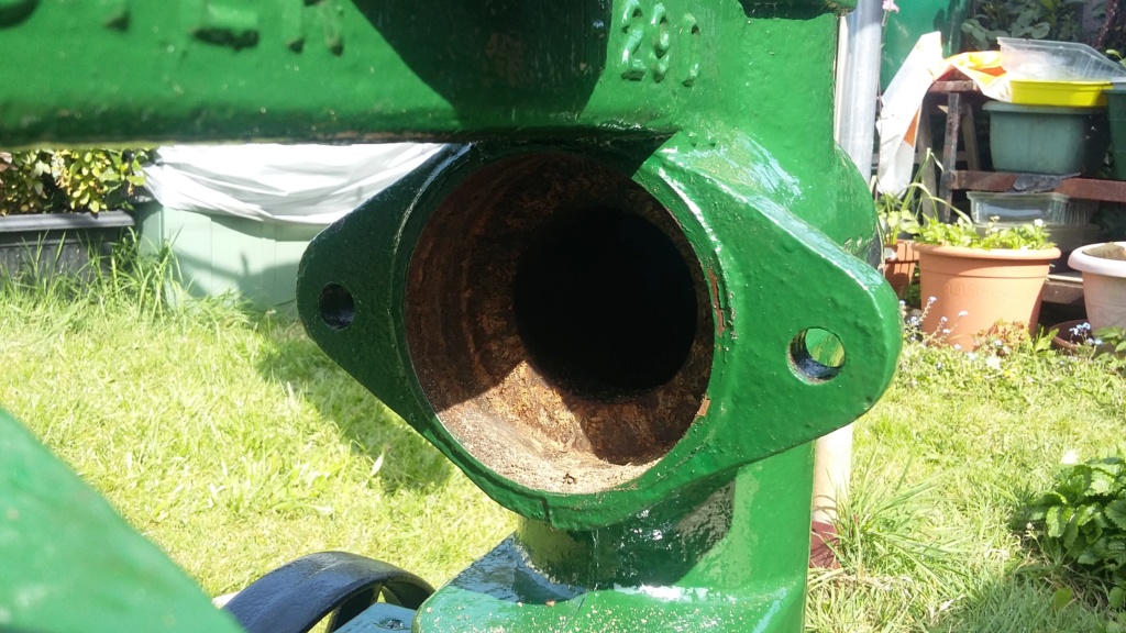
Gland packing removed, revealing the recessed stuffing box.
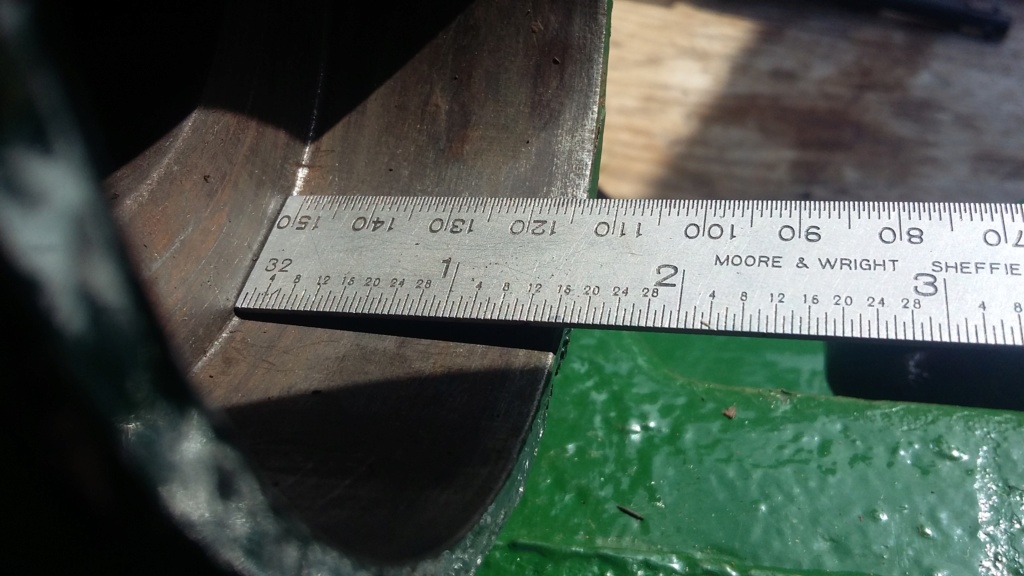
Housing cleaned up and depth measured.
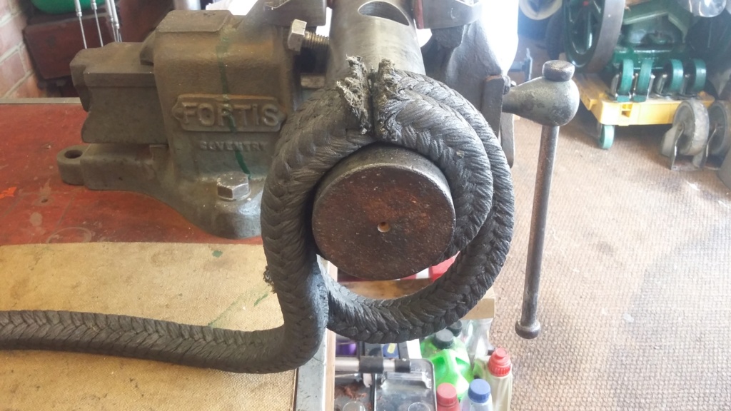
Packing being cut to length.
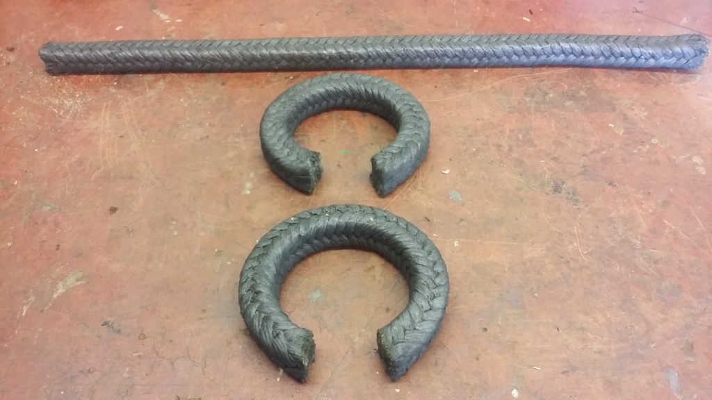
Two layers of new packing prepared. The off cut is 1" too short to make the other two required. I'll need to decide if to use one layer of graphite and one of PTFE or two of PTFE.
This is where I have to admit that I had not fully understood how the gland packing material is fitted. I initially thought that I was just replacing the pieces that had come away with the gland plates, I hadn't realised that the spindle bore was recessed, forming what I now believe is called a stuffing box! On closer inspection I could see the old gland packing was still inside the pump and needed to be extracted. Fortunately I have been supplied with new packing material, instructions and an extraction tool. Armed with the knowledge of what was required, I extracted the old packing and cleaned up the housing, ready for the replacement to be fitted. I have also cut two of the four new packing rings ready to be installed but I'm slightly nervous about actually fitting them. Instructions suggest the use of a split sleeve to insert the packing, not having one of these I will have to improvise but that will have to wait for another day. Tomorrow our road is having a socially separated V.E. Day street party in our front gardens, with appropriate music, food, drinks and I hope to exhibit the WW2 Jowett generator set and my 1919 "Victory" Model M Petter, neighbours willing!

Pump reunited with the repainted trolley.

This is what I thought the packing consisted of.

Closer inspection shows the packing is recessed into a stuffing box. I thought the inner edge was part of the casting.

Extraction tool in use.
!

Old packing removed from casting.

Gland packing removed, revealing the recessed stuffing box.

Housing cleaned up and depth measured.

Packing being cut to length.

Two layers of new packing prepared. The off cut is 1" too short to make the other two required. I'll need to decide if to use one layer of graphite and one of PTFE or two of PTFE.
Last edited by neil (LE) on Thu May 07, 2020 7:39 pm; edited 1 time in total (Reason for editing : corrected wording.)
neil (LE)- A credit to the forum

- Posts : 399
Join date : 2012-03-21
Age : 68
Location : N/W Kent
 Re: Lister H4 Pump Disassembly
That/s a shame as that/s all i had but ether will work good luck with it and I think I know the feeling to be short of a 1"
tony RA- A credit to the forum

- Posts : 279
Join date : 2013-11-16
Age : 77
Location : newtown powys
 Re: Lister H4 Pump Disassembly
That's not a plain scarf joint you've done there, is it? I did explain that's what was required on Page 1, the idea being that the joint on each ring of packing is tightened up against itself when the compression nuts are tightened. Now you won't know if it's water flowing between the seal and piston to lubricate it, or water just leaking through those joints, that's producing the few drops or water per minute leakage that's recommended.
Possible options? Buy some more packing and do a proper job, or just put it together as it is and hope it doesn't matter.
Possible options? Buy some more packing and do a proper job, or just put it together as it is and hope it doesn't matter.
_________________
Jules.

A Lister- A true Stationary engine owner

- Posts : 166
Join date : 2013-01-04
Location : South Cheshire
 Re: Lister H4 Pump Disassembly
Tony thanks, I will decide what to use, once I have cleared up exactly what to do about the scarf joint issue, as raised by Jules (AKA A Lister). I hope you have received the letter I sent to you, I think it was sent last Monday. It's always that last inch, that is all important!
Jules, yes sorry guilty as charged but I would like to put forward impatience, ignorance and limited ability, as my defence for so far failing to follow your advice on the scarf joint. I much appreciate all the help and assistance received through the forum and I would be a lot worse off without it. I did look up scarf joint as you suggested but I found it very confusing, as there seem to be a vast variety of options for these joints and most of them were for use in carpentry. I should have asked for help at that time but failed to do so. I then received some suitable packing to use which allowed me to proceed with the work. In the absence of a full understanding of the Scarf joint and the desire to proceed, I decide to go ahead with the butt joint. What tipped the balance, apart from being impatient and not confirming how to do it properly, was the instructions received with the material. This showed how to cut the material, by wrapping it around a former a number of times and then to straight cut them, to produce the rings. I also found it hard to cut the packing, having a large cross sectional area, the material easily deforms and anything other than a short straight cut was beyond my hand tools and ability. I may have acted in haste to repent at leisure but I think we all do this at times. What I now need to do, is to decide what to do going forward. Do I attempt a scarf joint (once I know precisely which one to use) for the other end, redo the first one or just carry on with what I've done so far.
Regards, Neil.
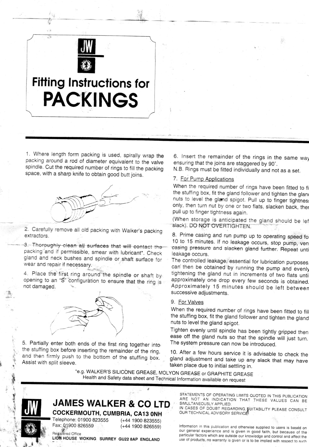
Instructions received with the packing material.
Jules, yes sorry guilty as charged but I would like to put forward impatience, ignorance and limited ability, as my defence for so far failing to follow your advice on the scarf joint. I much appreciate all the help and assistance received through the forum and I would be a lot worse off without it. I did look up scarf joint as you suggested but I found it very confusing, as there seem to be a vast variety of options for these joints and most of them were for use in carpentry. I should have asked for help at that time but failed to do so. I then received some suitable packing to use which allowed me to proceed with the work. In the absence of a full understanding of the Scarf joint and the desire to proceed, I decide to go ahead with the butt joint. What tipped the balance, apart from being impatient and not confirming how to do it properly, was the instructions received with the material. This showed how to cut the material, by wrapping it around a former a number of times and then to straight cut them, to produce the rings. I also found it hard to cut the packing, having a large cross sectional area, the material easily deforms and anything other than a short straight cut was beyond my hand tools and ability. I may have acted in haste to repent at leisure but I think we all do this at times. What I now need to do, is to decide what to do going forward. Do I attempt a scarf joint (once I know precisely which one to use) for the other end, redo the first one or just carry on with what I've done so far.
Regards, Neil.

Instructions received with the packing material.
neil (LE)- A credit to the forum

- Posts : 399
Join date : 2012-03-21
Age : 68
Location : N/W Kent
 Re: Lister H4 Pump Disassembly
I/d put the packings in put the joints opposite each other and put it back together and see how it goes it would be a shame to spend a lot of £/s on more packing with the piston so pitted and easy to change anyway go for it Neil the instructions were supplied by the packing manufacturer i/d go with that
tony RA- A credit to the forum

- Posts : 279
Join date : 2013-11-16
Age : 77
Location : newtown powys
 Re: Lister H4 Pump Disassembly
Hi there, I had the same issues as you when I tried to cut the packing(graphite). I purchased a proper gasket cutter, but every time I tried to do some sort of scarf joint the packing just deformed and looked a mess. I cut the packing at a clean 90' and tried the pump, It seems to be working ok, pumps has been running for a couple hours and no leaks!
Hope you get it sorted! Pump looks great by the way!
Julian
Hope you get it sorted! Pump looks great by the way!
Julian
68jcb- A true Stationary engine owner

- Posts : 143
Join date : 2019-01-17
Age : 56
Location : Redruth Cornwall
 Re: Lister H4 Pump Disassembly
Hi Neil yes will you thank you to you/r good lady for the card and contents
tony RA- A credit to the forum

- Posts : 279
Join date : 2013-11-16
Age : 77
Location : newtown powys
 Re: Lister H4 Pump Disassembly
Hi, for the last couple of days I have been suffering with swollen glands and have been trying to get them down to size, so they will squeeze in and fit. Obviously I'm talking about the packing glands on the pump, not any on my person. However I have suffered some pain and stress whilst attempting deal with the oversized gland issue. As I mentioned, I have received some packing material and had previously cut a couple of rings to length. I did take the easier option of cutting them as a butt, rather than the recommended scarf joint, hoping that overall it would prove the most expedient way, rather than necessarily being best practise. As per the instructions, I refitted the pump ram and then, starting at the joint, I attempted to gently insert the packing around the ram and into the stuffing box. This proved to be quite a challenge, especially as I did not have a split collar as mentioned in the instructions. In lieu of the collar, I used a thin block of wood, the width of the packing and lightly tapped around the circumference, until the packing eased into the void. Once in, I fitted the gland collar and tightened it up to press the packing home as best I could. I then attempted to follow this success with the second packing ring, unfortunately I just could not get this to fit properly. Using the same approach, I inserted the ring with the joint offset and tried to press it in against the first ring. This was only partially successful, as it would not enter any further than about two thirds of the way in. I even reversed the gland collar, to use the flat side to press the packing in but could not achieve a satisfactory result, with too much packing still exposed, external to the housing.
I retired indoors, hurt, to collect my thoughts and have a relaxing beer. When I thought about it, I had noticed that when the packing material was formed into the circle, the inner edge deformed and squeezed out, increasing the overall thickness to the point where it exceeded the housing dimensions. I had initially used the graphite packing which although softer than the PTFE, it did loose its shape more and it was this that was causing the difficulties. Today I cut a pair of rings from the PTFE material I had, which seemed to hold its shape a lot better, as well as being easier to cut. In fact I think I could have formed a scarf joint but I didn't realise that until after I had cut the joints. For the second time, I attempted to install the packing gland material, using the same procedure as before. This time I seem to have been successful, with the two rings having been inserted and pressed home, I can now use the gland plates to properly press up the gland material within the housing. I won't be able to confirm success until I've completed the other end and tested the pump for operation. Hopefully I'll be able to proceed onto the other end tomorrow and I think I might attempt a scarf joint, especially as I think I now understand how they are cut, although I don't know what the angle is and therefore what the length of the cut should be. At least some form of progress is being achieved.
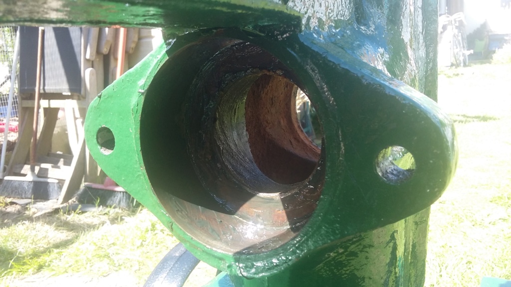
Housing all greased up and prepared to accept the packing material.
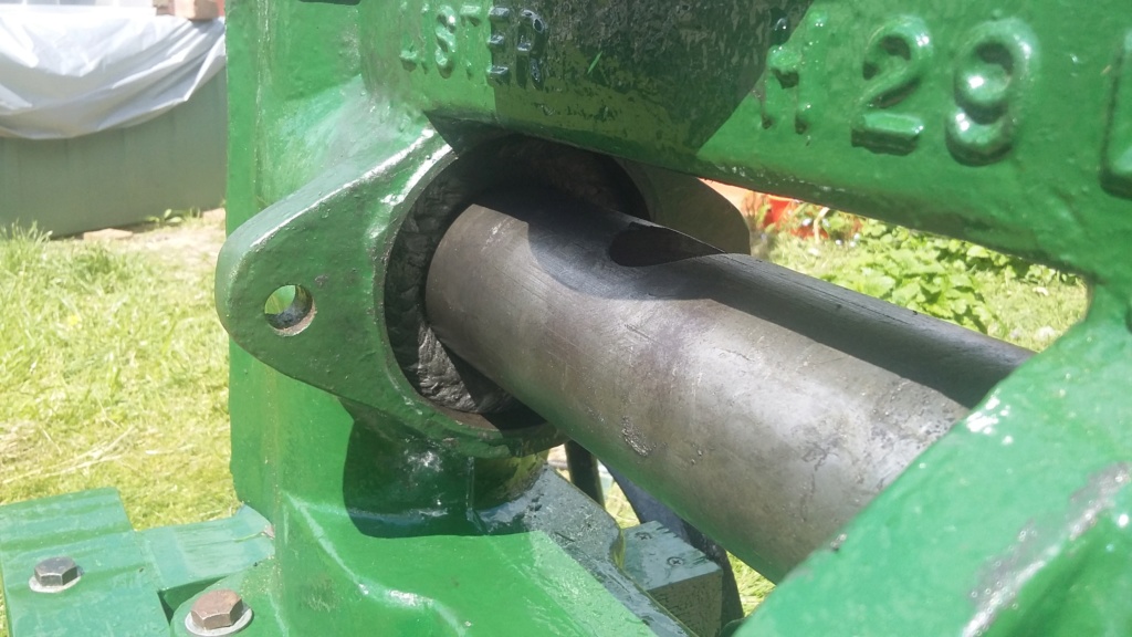
First graphite ring fitted inside housing
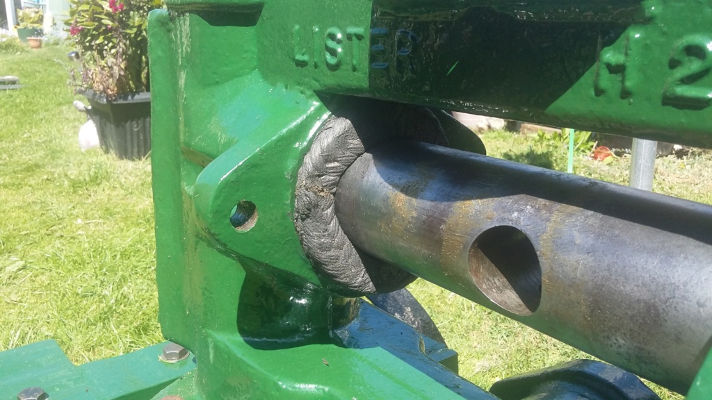
Second ring being fitted but will not press home.
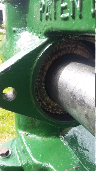
First PTFE ring fitted.
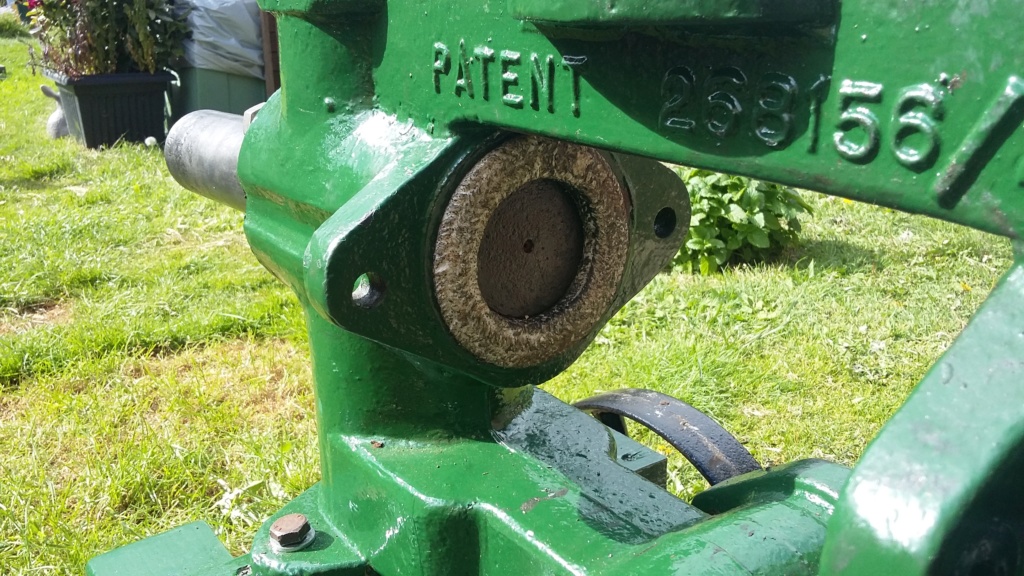
Second PTFE ring being gently pressed over the ram.
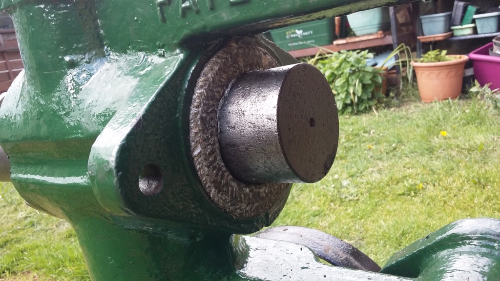
Almost there.
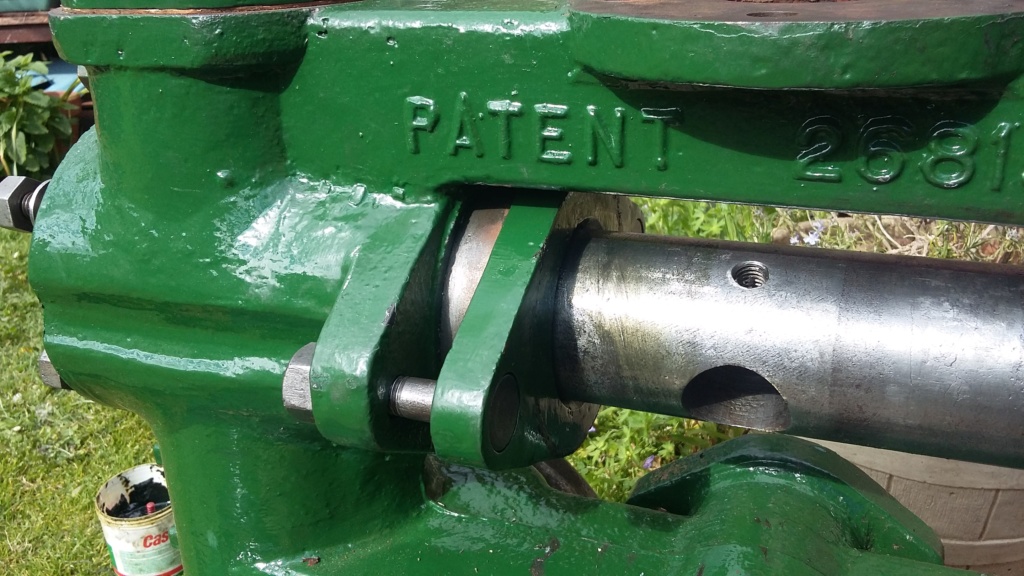
Packing clamp fitted and tightened up correctly.
I retired indoors, hurt, to collect my thoughts and have a relaxing beer. When I thought about it, I had noticed that when the packing material was formed into the circle, the inner edge deformed and squeezed out, increasing the overall thickness to the point where it exceeded the housing dimensions. I had initially used the graphite packing which although softer than the PTFE, it did loose its shape more and it was this that was causing the difficulties. Today I cut a pair of rings from the PTFE material I had, which seemed to hold its shape a lot better, as well as being easier to cut. In fact I think I could have formed a scarf joint but I didn't realise that until after I had cut the joints. For the second time, I attempted to install the packing gland material, using the same procedure as before. This time I seem to have been successful, with the two rings having been inserted and pressed home, I can now use the gland plates to properly press up the gland material within the housing. I won't be able to confirm success until I've completed the other end and tested the pump for operation. Hopefully I'll be able to proceed onto the other end tomorrow and I think I might attempt a scarf joint, especially as I think I now understand how they are cut, although I don't know what the angle is and therefore what the length of the cut should be. At least some form of progress is being achieved.

Housing all greased up and prepared to accept the packing material.

First graphite ring fitted inside housing

Second ring being fitted but will not press home.

First PTFE ring fitted.

Second PTFE ring being gently pressed over the ram.

Almost there.

Packing clamp fitted and tightened up correctly.
neil (LE)- A credit to the forum

- Posts : 399
Join date : 2012-03-21
Age : 68
Location : N/W Kent
 Re: Lister H4 Pump Disassembly
Well Neil it is bit of fiddle but there in so you/r on the right side of it you won/t be long now untill you/l be pumping
All the best with it
All the best with it
tony RA- A credit to the forum

- Posts : 279
Join date : 2013-11-16
Age : 77
Location : newtown powys
 Re: Lister H4 Pump Disassembly
Getting there Tony but only with your help.
Cheers, Neil.
Cheers, Neil.
neil (LE)- A credit to the forum

- Posts : 399
Join date : 2012-03-21
Age : 68
Location : N/W Kent
 Re: Lister H4 Pump Disassembly
Today I was able to continue with installing the seals at the opposite end of the pump. Having found the PTFE packing to be more manageable when being cut, I decided to attempt to produce and use a scarf joint as recommended previously. I wasn't totally convinced that I knew exactly what was required but I continued and produced what I thought and hoped, was correct. Once cut, I fitted the first ring and pressed it home, using the packing plate as with the first end. With fingers crossed, I produced the second ring with the scarf joint and fitted that in the housing, making sure the joints did not align, then tapped it home. It all looked quite good, even though with the two rings fitted the housing was totally full, which did not allow the packing plate to enter the recess by very much. This was to prove to be a problem, as when I attempted to turn the pump over, to check its action, I found that the cross shaft fouled on the packing plates at both ends. As I tightened the clamps up, to provide the necessary clearance, then the pump shaft seized. I found it necessary to go through a cycle of tightening the clamps, leaving them for a while, loosening and then re-tightening. After going through this procedure a number of times, I was just about able to achieve a minimum clearance at the clamp plates but I don't know if it is sufficient, whilst still being able to move the main shaft by turning the pulley, albeit with it feeling very tight. I will leave the clamps tightened up for a couple of days, to see if the packing settles in, to the compressed state. Normally I would release the clamp pressure, if the pump wasn't going to be used for a while but I feel that the new seals need to normalise in their housings, to allow further adjustment and hopefully provide the water seal as required. I have considered dry running the pump with just a little lubricant, rather than pumping water, in an attempt to run the seals in but I don't know if that will cause more issues than it would improve things. If it is recommended that I do not run the pump without water, then I will have to wait until I have the complete setup available, before I can see if I've been successful or not.
All the best, Neil.
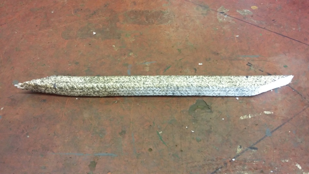
Packing cut to length, utilising a scarf joint?
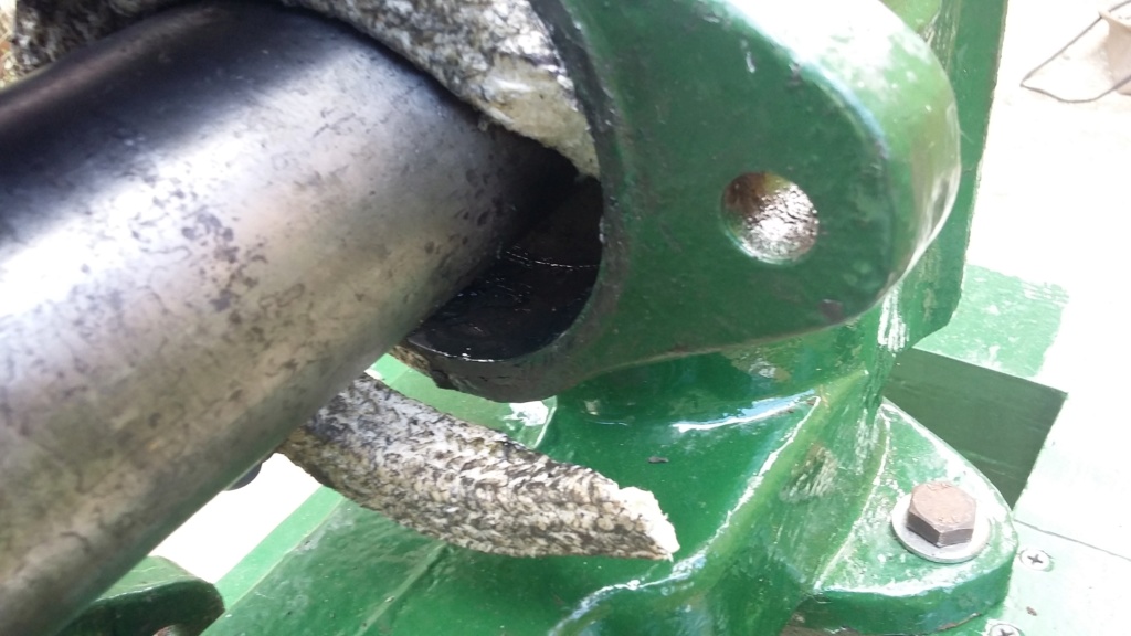
Packing being inserted with the scarf joint in use.
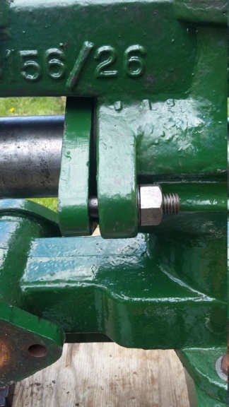
First ring being pressed home with the packing plate.
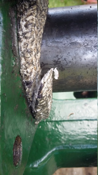
Second ring inserted, showing the scarf joint overlap.
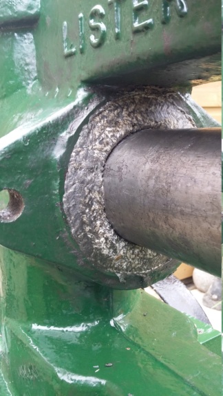
Second ring fitted, with joint ends pressed together. Hopefully providing the seal required.
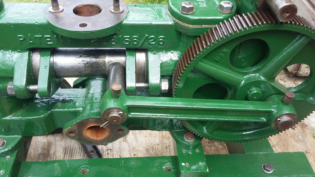
Cross shaft fouling the packing plate.
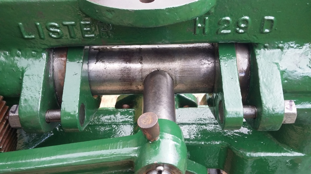
Packing plates adjusted up to allow full movement of pump ram, although very tight.
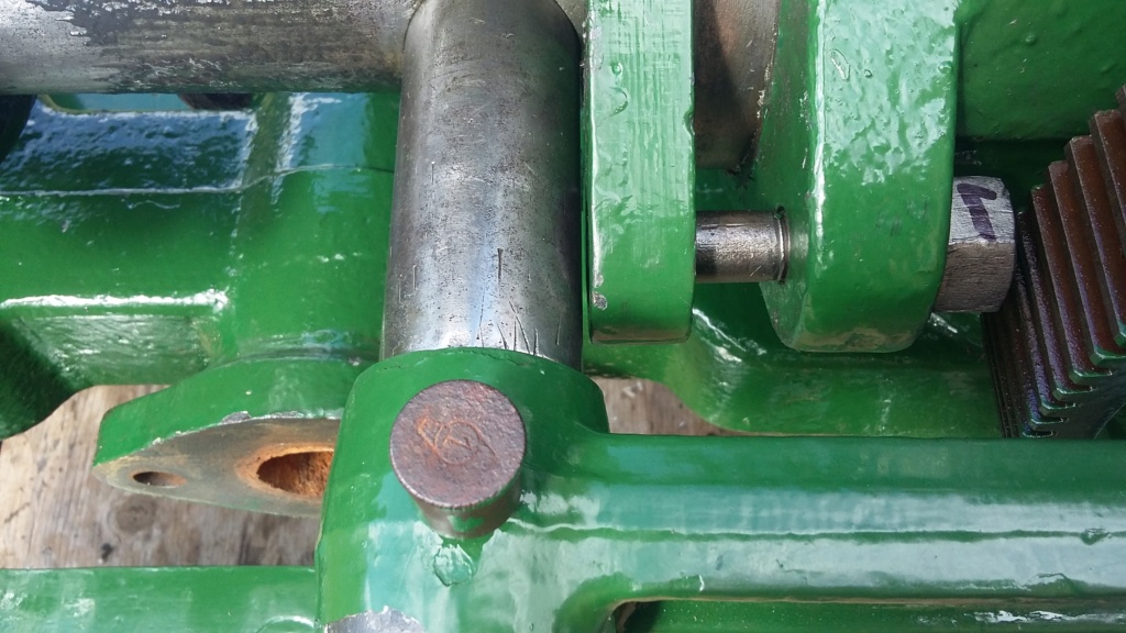
Clearance achieved but is it sufficient for safe use?
All the best, Neil.

Packing cut to length, utilising a scarf joint?

Packing being inserted with the scarf joint in use.

First ring being pressed home with the packing plate.

Second ring inserted, showing the scarf joint overlap.

Second ring fitted, with joint ends pressed together. Hopefully providing the seal required.

Cross shaft fouling the packing plate.

Packing plates adjusted up to allow full movement of pump ram, although very tight.

Clearance achieved but is it sufficient for safe use?
neil (LE)- A credit to the forum

- Posts : 399
Join date : 2012-03-21
Age : 68
Location : N/W Kent
 Re: Lister H4 Pump Disassembly
Well done, your scarf joint looks a nice, neat job, even better than the ones I managed for my pump. I used PTFE packing on my H2 and it seems to work fine, I chose it in preference to graphite as I thought it might be slightly more slippery and cause less wear on the ram. Realistically, for the amount we're likely to use these pumps at shows I doubt we'll notice a difference, but maybe the pump will run more freely if there's less friction.
Talking of which, I'm sure the packing will bed in a bit, and as long as it's not too tight and there's enough clearance between the cross head and the gland clamps for the pump to run properly then I doubt it will be a problem. It should certainly give a degree of future proofing where packing compression is concerned! As the saying goes, what will do a lot will also do a little - but not the other way round.
Keep us posted and never be tempted to try and lubricate the ram when the pump is running, as it's a good way to get your fingers crushed off between the cross head and the clamp, or chewed off in those unguarded gears! I know it seems obvious, but it's so easy to be tempted into doing something daft when 'fine tuning' a bit of vintage kit you've just restored. It's actually quite a dangerous design when you think about it, the clearance between the cross head and those clamps is just right for crushing or even amputating a finger or two! I speak from experience here as I had a very lucky escape with mine once!
_________________
Jules.

A Lister- A true Stationary engine owner

- Posts : 166
Join date : 2013-01-04
Location : South Cheshire
 Re: Lister H4 Pump Disassembly
Hi Jules, thanks for your comment on the scarf joint, as I wasn't actually sure that I had formed it correctly. Your confirmation is reassuring, hopefully meaning that when I get things up and running it should actually work.
As I noted in my last post, I left the gland clamps tightened up overnight to try to compress the packing and I fully expected to struggle to turn the pump over this morning. I was therefore much relieved to find that once I had broken the grease seal, I was able to turn the pulley wheel over relatively easily. Hopefully a good sign, for future operation.
I have duly noted your safety advice and dire warnings with regard to the dangers of tampering with the pump while it's operating. In fact your comment of your lucky escape, made me wince at the thought of it. I shall be keeping my fingers well away. As we used to say at work "ne pas de finger pocken".
Neil.
neil (LE)- A credit to the forum

- Posts : 399
Join date : 2012-03-21
Age : 68
Location : N/W Kent
 Re: Lister H4 Pump Disassembly
Hi all, well what have I been up to since my last post. Not a lot in the way of actual progress really, I have basically been undertaking remedial work, in fact one step forward and two steps back. I had originally used some timber I had available that was 2.5" x 1.75" for the cross members, to support the pump on the trolley. Although this worked it didn't look correct, the pump looked as though it was perched on the cross members. I decided to use some wood I had left over from the old trolley that was 6" x "2, this would look better with the whole of the foot bearing on the cross member. Having cut this to size and produced the fixing holes, the pieces were prepped and painted ready to be fitted. Only to find that when they were fitted, once the weight of the pump rested on them and the bolts were tightened up the wood split across its length. So for the third time I produced the cross members, this time from some decent wood, which if I had realised it was there earlier, I would have used it in the first place! Again this was cut, fixing holes made and then went through the full painting process yet again. As the wood had been rough cut, it needed some serious sanding down to make it look respectable before it could be painted.
Having now got back to where I was a couple of weeks earlier, I could now start to put everything back together again. I've cut some new gaskets from sheet rubber, for the air vessel, the priming flange, and the inlet connection. If these will work, only time will tell but is all I had available. I have re-checked that the pump can still be turned over by hand, using the drive pulley and it can. However as it is quite stiff, I wonder if the poor old Lister D will be up to the job, I hope it will be capable to at least turn the pump over, to prove the pump does actually operate. To enable this to happen, I have started to clean up and paint the Lister, ready to reassemble it, so it can be used for the trial run of the H4 pump. So hopefully not too much more to actually do on the pump, although I have not got all the nuts and washers to hand, that are needed to properly fix the pump to the cross bearers and the bearers to the trolley. I will need to source these once the lock down is fully released and I am able to get to where I can get hold of some, until then what I have will do, at least to test run the pump.
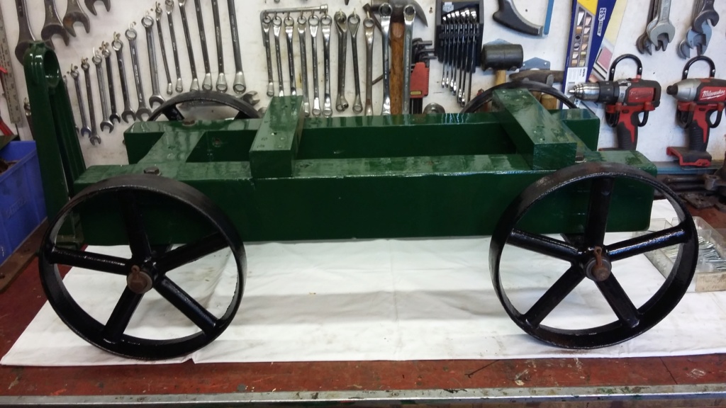
First style cross members being fitted to trolley
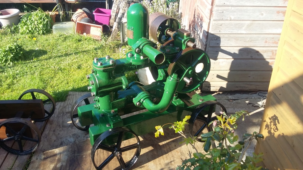
First style cross bearer fully fitted, with the pump looking as though it is perched on top.
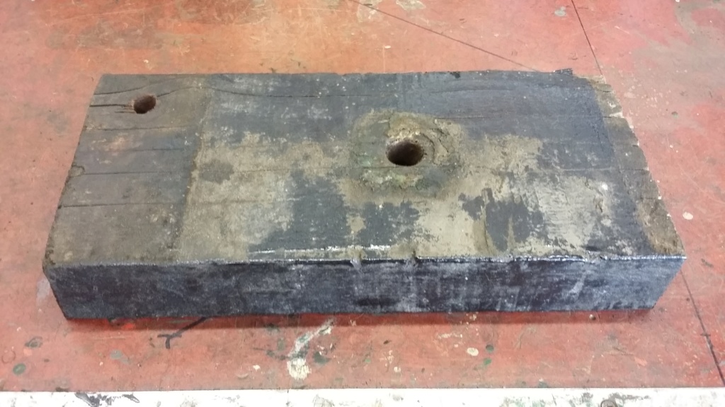
Wood as recovered from previous pump trolley, cut to size.

Split bearer having been taken back off the trolley.
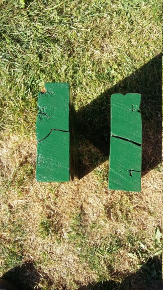
End splits on the bearers.
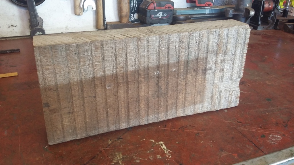
New piece of wood for cross bearer, showing how rough cut it was.
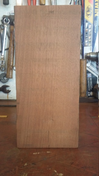
New timber hand sanded, ready for painting.
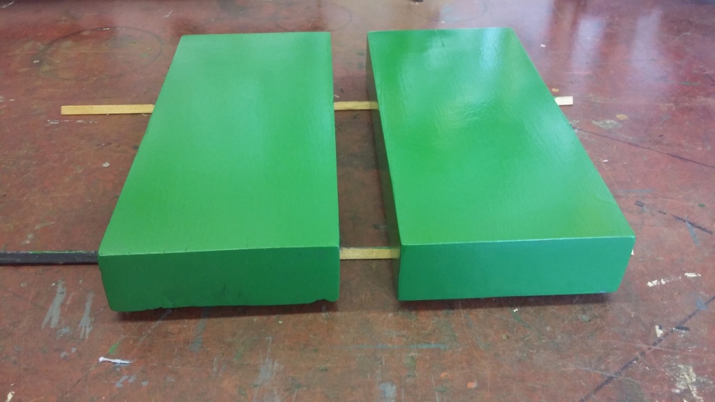
Undercoated cross members.
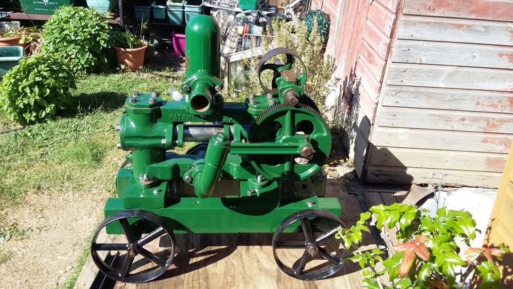
New cross members fitted, looking better than the first type.
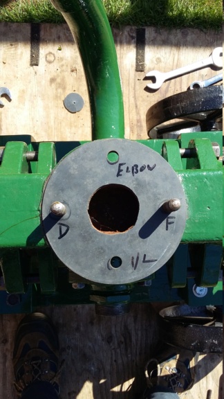
Rubber gasket being fitted to the air vessel joint.
Having now got back to where I was a couple of weeks earlier, I could now start to put everything back together again. I've cut some new gaskets from sheet rubber, for the air vessel, the priming flange, and the inlet connection. If these will work, only time will tell but is all I had available. I have re-checked that the pump can still be turned over by hand, using the drive pulley and it can. However as it is quite stiff, I wonder if the poor old Lister D will be up to the job, I hope it will be capable to at least turn the pump over, to prove the pump does actually operate. To enable this to happen, I have started to clean up and paint the Lister, ready to reassemble it, so it can be used for the trial run of the H4 pump. So hopefully not too much more to actually do on the pump, although I have not got all the nuts and washers to hand, that are needed to properly fix the pump to the cross bearers and the bearers to the trolley. I will need to source these once the lock down is fully released and I am able to get to where I can get hold of some, until then what I have will do, at least to test run the pump.

First style cross members being fitted to trolley

First style cross bearer fully fitted, with the pump looking as though it is perched on top.

Wood as recovered from previous pump trolley, cut to size.

Split bearer having been taken back off the trolley.

End splits on the bearers.

New piece of wood for cross bearer, showing how rough cut it was.

New timber hand sanded, ready for painting.

Undercoated cross members.

New cross members fitted, looking better than the first type.

Rubber gasket being fitted to the air vessel joint.
neil (LE)- A credit to the forum

- Posts : 399
Join date : 2012-03-21
Age : 68
Location : N/W Kent
 Re: Lister H4 Pump Disassembly
In over 40 years of buggering about with old engines and pumps I've never used a scarf joint on gland packing and never had a problem, with the smaller pumps like the Lee Howl Super Major, Domestic, Leo etc. what I've done with them is just wrapped the packing round the shaft a couple of times and cut to lenght so it was just 1 piece.
As for fudging it into the gap, again I've nipped my packing in the jaws of a vice so it was squished down in thickness, put it in then done up the retaining plates/nuts depending on what pump it is. Should have a small amount of seapage to just keep the gland sweet but not too much.
As for fudging it into the gap, again I've nipped my packing in the jaws of a vice so it was squished down in thickness, put it in then done up the retaining plates/nuts depending on what pump it is. Should have a small amount of seapage to just keep the gland sweet but not too much.

Appletop- Life Member

- Posts : 1483
Join date : 2010-01-02
Age : 56
Location : Just outside Diss
Page 3 of 6 •  1, 2, 3, 4, 5, 6
 Similar topics
» Lister 'd' to lister domestic pump
» Lister H1 pump nut
» Lister Domestic Pump
» Lister domestic pump help ....
» Lister H3 pump
» Lister H1 pump nut
» Lister Domestic Pump
» Lister domestic pump help ....
» Lister H3 pump
Page 3 of 6
Permissions in this forum:
You cannot reply to topics in this forum