Lister H4 Pump Disassembly
+8
chrismac
neil (LE)
Foden
Robotstar5
oldgit
tony RA
68jcb
matthew92
12 posters
Page 5 of 6
Page 5 of 6 •  1, 2, 3, 4, 5, 6
 Re: Lister H4 Pump Disassembly
Maryalice, as they say, if you catch them young enough, you've got them for life. Sounds like your grandson is in good hands, let's hope he takes to it.
More preparation and paint work undertaken today. Crank assembly prepped and both the timing and crank assemblies were given a coat of primer. Rubbing back the crank assembly proved a little awkward, due to its construction, just had to do it by hand, using emery paper. Not much else achieved apart for a couple of small items given a coat of gloss.
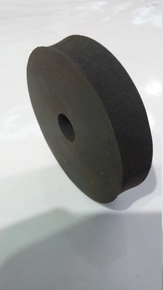
Looked through the new parts I had received for the pump, with the idea of fitting the replacement pump valve washers. Unfortunately they have been manufactured with an undersized centre hole, which will not go over the studs, let alone the little bush they are meant to slide up and down on. I have spoken to the supplier and they acknowledged there is an issue with the items but have also realised their whole stock is the same. They have suggested I can either attempt to open out the hole myself, or send them back and they will do it for me. They did agree that I could try and if I wasn't happy with the result, I could still send them back for replacement. So I think I will go that route, give it a go and if not successful, send them back. It's just frustrating that there always seems to be something wrong, when you purchase items remotely.
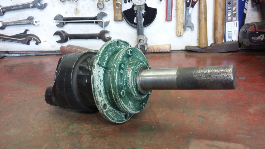
Crank assembly prepped, ready for a primer base coat.
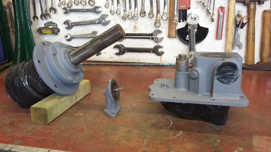
Assemblies primed and ready for the next layer, of undercoat.

Small items, top coated.
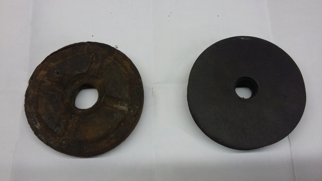
Old washer on the left, note the larger hole as compared with the new item on the right.
More preparation and paint work undertaken today. Crank assembly prepped and both the timing and crank assemblies were given a coat of primer. Rubbing back the crank assembly proved a little awkward, due to its construction, just had to do it by hand, using emery paper. Not much else achieved apart for a couple of small items given a coat of gloss.
Looked through the new parts I had received for the pump, with the idea of fitting the replacement pump valve washers. Unfortunately they have been manufactured with an undersized centre hole, which will not go over the studs, let alone the little bush they are meant to slide up and down on. I have spoken to the supplier and they acknowledged there is an issue with the items but have also realised their whole stock is the same. They have suggested I can either attempt to open out the hole myself, or send them back and they will do it for me. They did agree that I could try and if I wasn't happy with the result, I could still send them back for replacement. So I think I will go that route, give it a go and if not successful, send them back. It's just frustrating that there always seems to be something wrong, when you purchase items remotely.

Crank assembly prepped, ready for a primer base coat.

Assemblies primed and ready for the next layer, of undercoat.

Small items, top coated.

Old washer on the left, note the larger hole as compared with the new item on the right.
neil (LE)- A credit to the forum

- Posts : 399
Join date : 2012-03-21
Age : 68
Location : N/W Kent
 Re: Lister H4 Pump Disassembly
Neil,
Either make or buy a set of hole punch's for leather etc, you should be able to punch the hole larger or use a hand reamer and orpen them up that way but dont use a drill it will rip them to pieces.
Maryalice
Either make or buy a set of hole punch's for leather etc, you should be able to punch the hole larger or use a hand reamer and orpen them up that way but dont use a drill it will rip them to pieces.
Maryalice
maryalice- Life Member

- Posts : 1310
Join date : 2010-01-23
Age : 70
Location : Bedfordshire
neil (LE)- A credit to the forum

- Posts : 399
Join date : 2012-03-21
Age : 68
Location : N/W Kent
 Re: Lister H4 Pump Disassembly
A decent sharp punch will go through that.
maryalice- Life Member

- Posts : 1310
Join date : 2010-01-23
Age : 70
Location : Bedfordshire
 Re: Lister H4 Pump Disassembly
O.K. thanks, I'll give it a go. I've got nothing to loose, I'll see how I get on.
neil (LE)- A credit to the forum

- Posts : 399
Join date : 2012-03-21
Age : 68
Location : N/W Kent
 Re: Lister H4 Pump Disassembly
Hi, well I gave it a go and got mixed results. I initially attempted to cut one but used a punch that proved to be too small, so had to try to enlarge it again with a slightly larger punch. This meant the second cut was very close to the hole edge, making it difficult for the punch to cut properly, as the rubber collapsed under the pressure. It would certainly have been easier to punch all the holes into blank washers, rather than having to enlarge an existing hole. Unfortunately the choice of punches available resulted in a hole either too small or slightly too large. I'm not certain if the larger diameter hole will cause any issues with the operation of the pump but I will give it a try. As although I can return the seals for a refund, at present they cannot supply the correct replacements. Instead they have agreed that I can give them a try and if I have a problem later on they will still refund, or by then they might have new replacements available.
Neil.
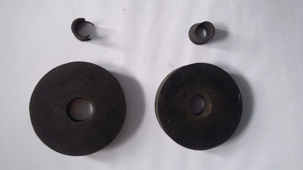
The first pair of modified washers, with over enlarged and out of shape holes. Also showing the incomplete cut out centres, which caused the rough bore.
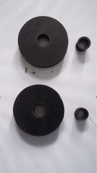
The second pair looking better, with the complete, centrally punched out off-cuts, resulting in the smooth bore.
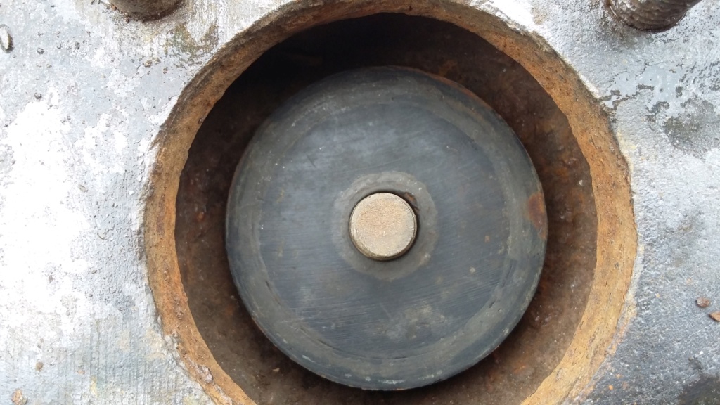
One of the better original washers in place , showing the fit on the spindle.
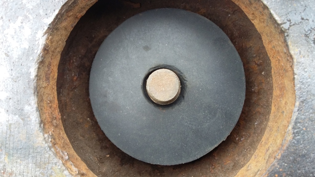
One of the badly cut seals in place, showing the large gap around the spindle. Will this cause an issue with the operation of the pump, only time will tell.
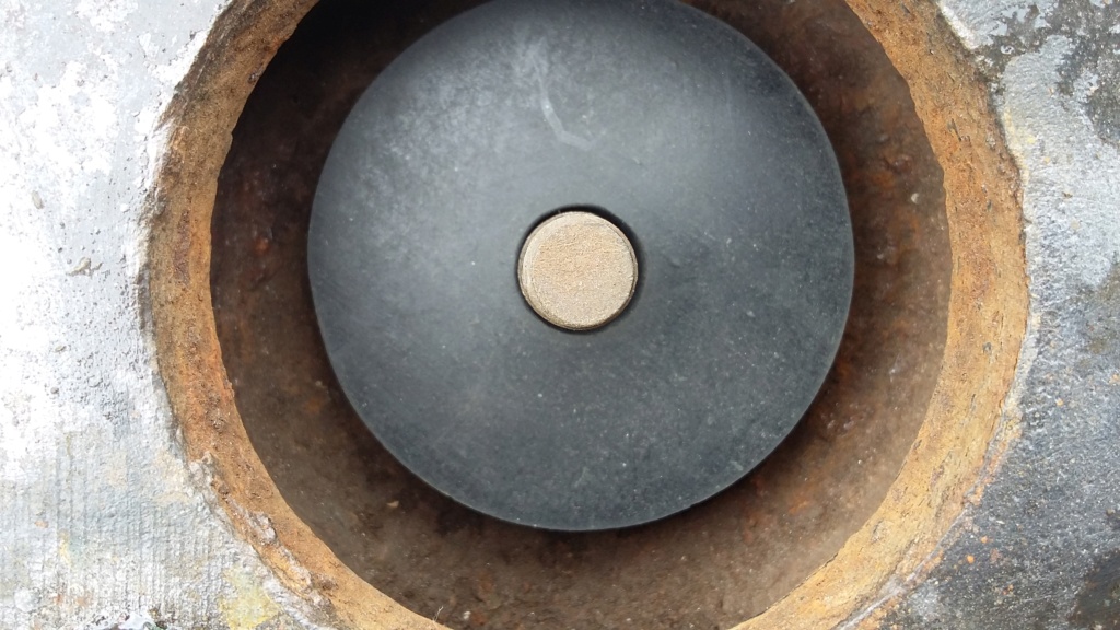
One of the good new seals fitted. Although loose on the spindle, hopefully it will operate correctly.
The other area of activity today was to continue with painting some of the last items left to complete. I had almost forgotten the governor unit, which had been put away for safe keeping. This was cleaned up and by the end of the day it had got to the undercoat stage, along with the primed items from yesterday. Slowly but surely getting there.
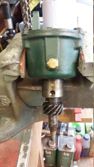
Governor unit being clean up, prior to painting.
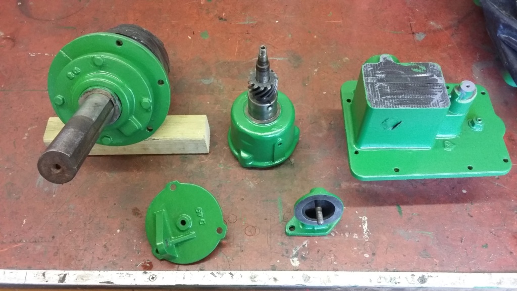
Last remaining items have now been painted in undercoat. Just the top coats to be applied.
Neil.

The first pair of modified washers, with over enlarged and out of shape holes. Also showing the incomplete cut out centres, which caused the rough bore.

The second pair looking better, with the complete, centrally punched out off-cuts, resulting in the smooth bore.

One of the better original washers in place , showing the fit on the spindle.

One of the badly cut seals in place, showing the large gap around the spindle. Will this cause an issue with the operation of the pump, only time will tell.

One of the good new seals fitted. Although loose on the spindle, hopefully it will operate correctly.
The other area of activity today was to continue with painting some of the last items left to complete. I had almost forgotten the governor unit, which had been put away for safe keeping. This was cleaned up and by the end of the day it had got to the undercoat stage, along with the primed items from yesterday. Slowly but surely getting there.

Governor unit being clean up, prior to painting.

Last remaining items have now been painted in undercoat. Just the top coats to be applied.
neil (LE)- A credit to the forum

- Posts : 399
Join date : 2012-03-21
Age : 68
Location : N/W Kent
 Re: Lister H4 Pump Disassembly
Whenever I've made new washers for a pump I've always just drilled the center hole out with a normal HSS drill bit. What I have done before now is used a copper pipe the right size for the outside of the valve and got that really hot and melted the washers out before drilling.

Appletop- Life Member

- Posts : 1483
Join date : 2010-01-02
Age : 56
Location : Just outside Diss
 Re: Lister H4 Pump Disassembly
Thanks "Appletop" I have found whenever I try to drill rubber, it can rip rather than cut cleanly, rather like "Maryalice" mentioned. I imagine if you have good sharp drill and get the chuck speed correct, then it can work well but I never know what speed to set the drill at, to ensure it cuts rather than rips. Hopefully what i have achieved will work out well enough in the end.
Following on from the last post, the last few items have been treated to their first layer of top coat. This will be allowed to harden off for a couple of days at least, before having a light rub down and a second application, to hopefully complete the job.
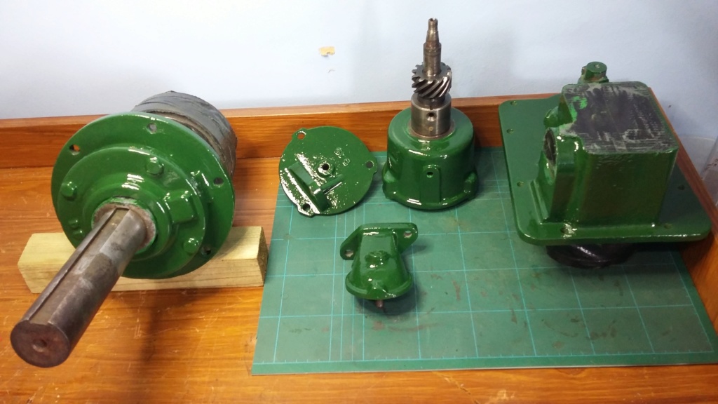
Last few items, in their first coat of engine enamel.
Following on from the painting, I returned to work on the head. I had previously removed the valves but hadn't undertaken any other work on them. So I took the opportunity to lightly grind the valves in to their respective seats, followed by a good clean up to ensure there was no grinding paste left on the valves or the seats. I then went onto reassembling the valves back into the head. To hold the valves in place I used a block of wood in the combustion chamber, as suggested in the instruction manual. I found some balsa wood which I cut to size easily, which I found worked quite well. Once I had everything back in place, I used some methylated spirit in the chamber to check for leaks around the valves. I used methylated spirits, as it is easy to see, is safer to use than petrol and hopefully has similar characteristic to petrol when looking for how well the valves are sealing. After about an hour, the fluid was still held in the head, with no indication of any wetness in the inlet or exhaust manifolds. The rocker shaft and rockers were also installed, just to confirm everything went back together, although they will need to be removed again, before the head can be fitted back onto the main engine block.
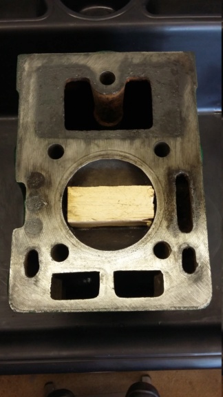
Valves being held in place with a piece of balsa wood cut to size.
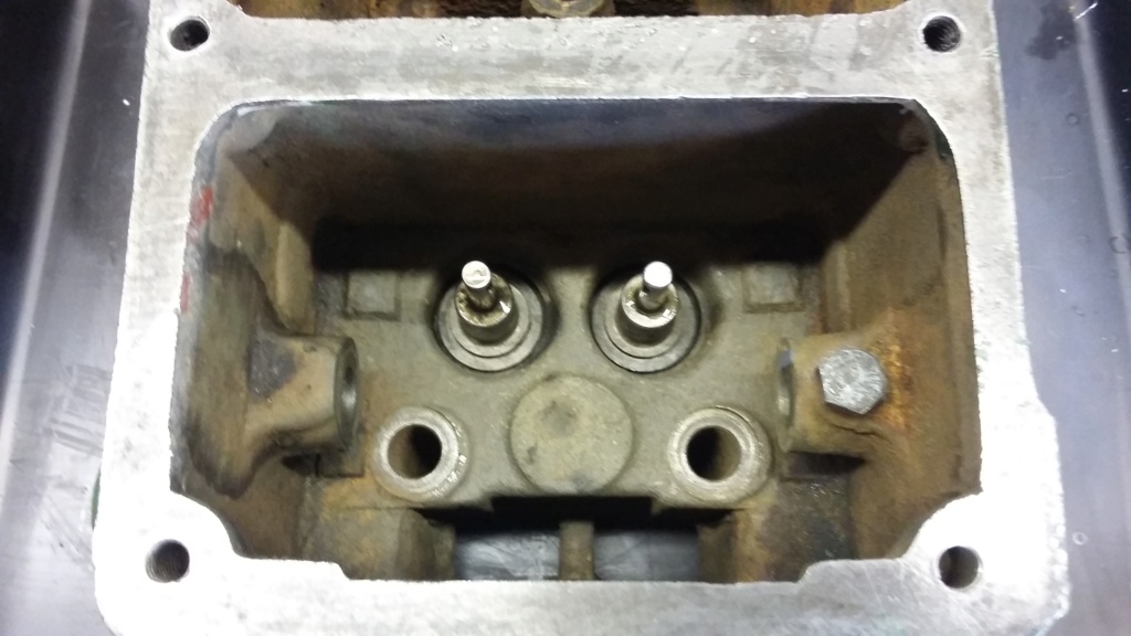
Valves inserted, held in place by the wood block.
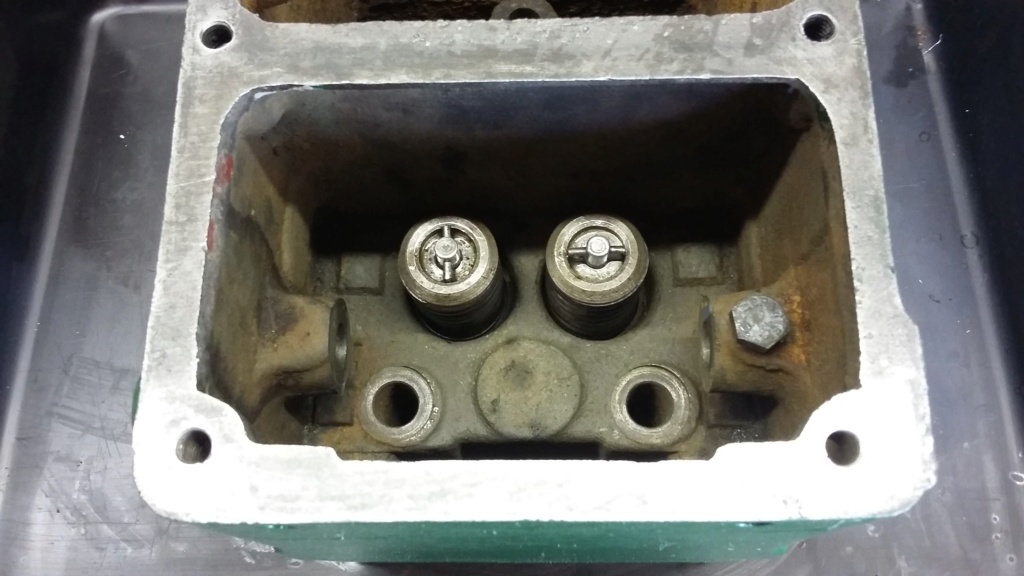
Valve springs, carrier and cotters fitted.

Methylated spirit being used as a leak test fluid, on the valve seats.
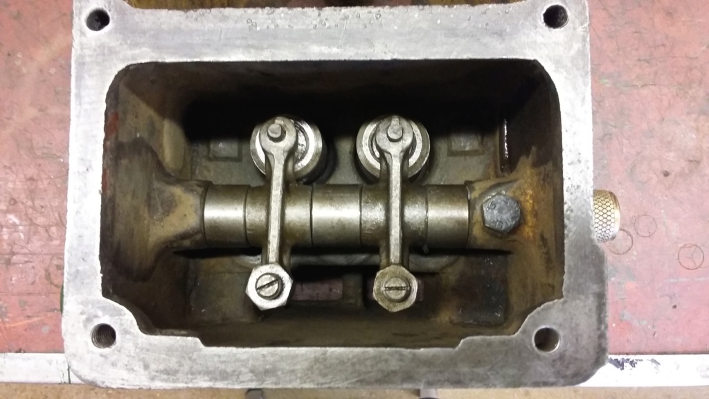
Rocker shaft and rockers temporarily replaced to confirm fit. Will need to be removed again, before head can be refitted to main engine block.
Following on from the last post, the last few items have been treated to their first layer of top coat. This will be allowed to harden off for a couple of days at least, before having a light rub down and a second application, to hopefully complete the job.

Last few items, in their first coat of engine enamel.
Following on from the painting, I returned to work on the head. I had previously removed the valves but hadn't undertaken any other work on them. So I took the opportunity to lightly grind the valves in to their respective seats, followed by a good clean up to ensure there was no grinding paste left on the valves or the seats. I then went onto reassembling the valves back into the head. To hold the valves in place I used a block of wood in the combustion chamber, as suggested in the instruction manual. I found some balsa wood which I cut to size easily, which I found worked quite well. Once I had everything back in place, I used some methylated spirit in the chamber to check for leaks around the valves. I used methylated spirits, as it is easy to see, is safer to use than petrol and hopefully has similar characteristic to petrol when looking for how well the valves are sealing. After about an hour, the fluid was still held in the head, with no indication of any wetness in the inlet or exhaust manifolds. The rocker shaft and rockers were also installed, just to confirm everything went back together, although they will need to be removed again, before the head can be fitted back onto the main engine block.

Valves being held in place with a piece of balsa wood cut to size.

Valves inserted, held in place by the wood block.

Valve springs, carrier and cotters fitted.

Methylated spirit being used as a leak test fluid, on the valve seats.

Rocker shaft and rockers temporarily replaced to confirm fit. Will need to be removed again, before head can be refitted to main engine block.
neil (LE)- A credit to the forum

- Posts : 399
Join date : 2012-03-21
Age : 68
Location : N/W Kent
 Re: Lister H4 Pump Disassembly
Looks like you're making good progress, and with a set of 'performance tuned' valves too! I bet they were never that tightly sealing when new!
Seeing that governor housing being painted reminded me of when I did the one on my 'Before and After' Lister D. When I removed the old paint I found someone had engraved two initials into the metal, something that had not been seen for over 70 years until the paint was removed:

A nice bit of history, but what are the chances of me finding those initials when restoring the engine? An even bigger and slightly spooky coincidence, they are actually my initials too! So I think it really was a case of that engine having my name on it!
A possible explanation for the initials was that Lister may have contracted out to another foundry for that casting due to wartime demand, and this was used as a mark to identify the contracted out parts from their own? The initials were also present on the governor bell housing too, but nowhere else on the engine, unless they're lurking under the original paintwork on the unrestored side.
Either way, it was one of those slightly odd occurrences in life that makes you stop and wonder if there's perhaps more to it than we currently understand.
Seeing that governor housing being painted reminded me of when I did the one on my 'Before and After' Lister D. When I removed the old paint I found someone had engraved two initials into the metal, something that had not been seen for over 70 years until the paint was removed:

A nice bit of history, but what are the chances of me finding those initials when restoring the engine? An even bigger and slightly spooky coincidence, they are actually my initials too! So I think it really was a case of that engine having my name on it!
A possible explanation for the initials was that Lister may have contracted out to another foundry for that casting due to wartime demand, and this was used as a mark to identify the contracted out parts from their own? The initials were also present on the governor bell housing too, but nowhere else on the engine, unless they're lurking under the original paintwork on the unrestored side.
Either way, it was one of those slightly odd occurrences in life that makes you stop and wonder if there's perhaps more to it than we currently understand.
_________________
Jules.

A Lister- A true Stationary engine owner

- Posts : 166
Join date : 2013-01-04
Location : South Cheshire
Robotstar5- Life Member

- Posts : 1110
Join date : 2018-09-25
 Re: Lister H4 Pump Disassembly
Stowmarket by any chance.
Maryalice
Maryalice
maryalice- Life Member

- Posts : 1310
Join date : 2010-01-23
Age : 70
Location : Bedfordshire
 Re: Lister H4 Pump Disassembly
QUALCAST!!  The two worse foundries we delivered limestone to, Sinfin wasn't that good but Smethwick was an absolute hell hole and a H&S nightmare, they both had a load every day so no escape!
  Thankfully they are gone now.
Pete.
Pete.
_________________
Too much to do, and so little time!!

Foden- Life Member

- Posts : 1411
Join date : 2009-11-04
Age : 73
Location : North Midlands
 Re: Lister H4 Pump Disassembly
[quote="maryalice"]Stowmarket by any chance.
Maryalice[/quote]
Nope, that was the Suffolk Iron Foundry.
Maryalice[/quote]
Nope, that was the Suffolk Iron Foundry.

Appletop- Life Member

- Posts : 1483
Join date : 2010-01-02
Age : 56
Location : Just outside Diss
 Re: Lister H4 Pump Disassembly
They become part of Qualcast, https://www.gracesguide.co.uk/Suffolk_Iron_Foundry_(1920) look at 1958.
Maryalice
Maryalice
maryalice- Life Member

- Posts : 1310
Join date : 2010-01-23
Age : 70
Location : Bedfordshire
 Re: Lister H4 Pump Disassembly
[quote="maryalice"]They become part of Qualcast, https://www.gracesguide.co.uk/Suffolk_Iron_Foundry_(1920) look at 1958.
Maryalice[/quote]
Yes they did but all they did there is assemble stuff, nothing was made since Qualcast took over, hasn't been for years, I'm not sure if they still build if I'm honest.
Maryalice[/quote]
Yes they did but all they did there is assemble stuff, nothing was made since Qualcast took over, hasn't been for years, I'm not sure if they still build if I'm honest.

Appletop- Life Member

- Posts : 1483
Join date : 2010-01-02
Age : 56
Location : Just outside Diss
 Re: Lister H4 Pump Disassembly
Atco's from birmingham were moved to Stowmarket, what it doesnt say was if they made or assembled.
What I do know is that when I did a lot of plane spotting, late 70's early 80's, I got to knowc a fella who worked in the foundry at Stowmarket.
Maryalice
What I do know is that when I did a lot of plane spotting, late 70's early 80's, I got to knowc a fella who worked in the foundry at Stowmarket.
Maryalice
maryalice- Life Member

- Posts : 1310
Join date : 2010-01-23
Age : 70
Location : Bedfordshire
 Re: Lister H4 Pump Disassembly
Foden wrote:QUALCAST!!The two worse foundries we delivered limestone to, Sinfin wasn't that good but Smethwick was an absolute hell hole and a H&S nightmare, they both had a load every day so no escape!
Thankfully they are gone now.
Pete.
I better keep quiet I was at one of the Smethwick foundries
_________________
Stuart

Robotstar5- Life Member

- Posts : 1110
Join date : 2018-09-25
 Re: Lister H4 Pump Disassembly
The Sinfin, Derby, plant did a lot of castings for both Ford and Perkins but lost a lot of business when Ford found it cheaper to have them done in Korea. We took 50mm limestone into the plant daily and Waters Transport from Darley Bridge brought artic loads of coke in from Spain several times a week.
Pete.
Pete.
_________________
Too much to do, and so little time!!

Foden- Life Member

- Posts : 1411
Join date : 2009-11-04
Age : 73
Location : North Midlands
 Re: Lister H4 Pump Disassembly
Hi it's been a week since my last post. Initially I was back to waiting for paint to dry, a frustrating time but necessary, if I'm not going to damage the finish. I do keep trying to remember that this is only meant to be a quick spruce up of the "D" to get the pump working. I have now removed all the masking and loosely rebuilt the main components, just to see how it looks. Luckily I remembered not to fully build the engine on the bench, otherwise I would never be able to get it down again.
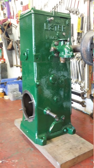
Dry build on the bench, no internals.
To be able to complete the rebuild, the donor trolley from my Lister A needed two cross bearers to be cut and fitted before I could mount the "D" onto it.
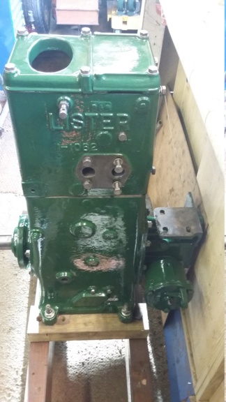
Main engine block mounted onto the donor trolley.
Once I had established a secure mounting for the engine on the trolley, I started to properly rebuild the engine's internals. This threw up a couple of issues that I thought I would share. The first issue was with the oil splash guard. On close inspection, I noted that a groove had been worn into the end of the slot in the guard, which had been caused by the dipper on the end of the connecting rod rubbing against it. I felt if I left as it was, it could cause damage to the dipper, possibly causing it to break off, with disastrous results. I decided to reduce the risk and remove a small amount material, to ensure the dipper did not rub on the guard.
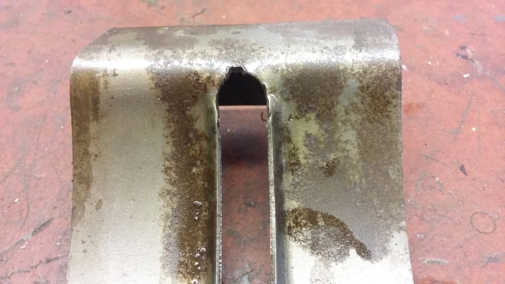
Notch worn into the end of the oil splash guard by the dipper.
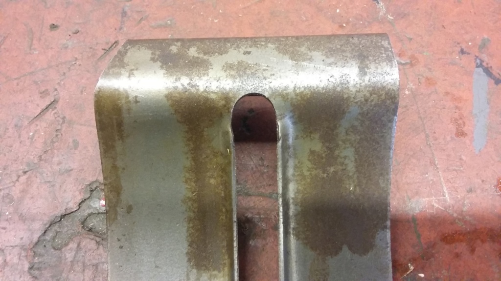
End of oil splash guard filed out to clear dipper.
Once the guard had been modified, it was refitted and checked to ensure the dipper no longer fouled it and all seemed to be fine. The only other issue I came across, was with the gasket on the front of the governor casting. I had bought a new set of gaskets but when I went to fit this one, it appeared to be the wrong size. The inner edge of the housing is 3 7/16th diameter but the gasket outer diameter is only 3 3/4" with the inner diameter of 2 15/16th, which only leaves 5/32" around the edge to seal the joint, the rest of the gasket is useless being inside the housing. When I queered this with the supplier, they were helpful and went back to the original drawings and they confirmed they were correct to the drawings but equally couldn't understand why they fitted the way they did. Was this a drawing office error which has been copied for decades, or is there an alternative reason for this design? Anybody on here with any suggestions as to why these gaskets were designed and made like this.
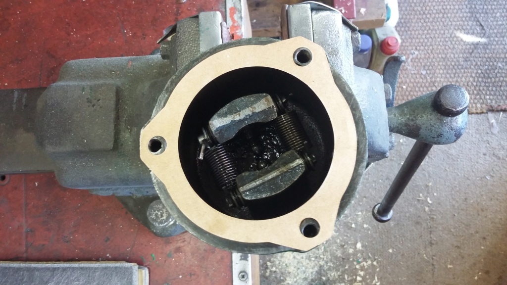
Gasket positioned on housing, showing how little is actually on the machined surface.
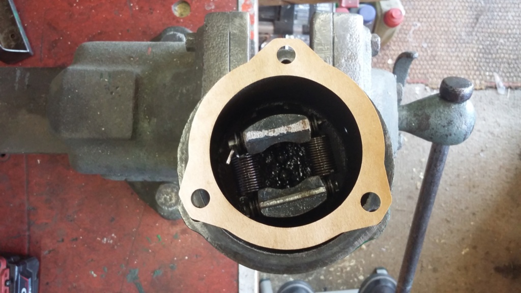
Gasket placed on housing, demonstrating the width seems to be correct, just the diameter appears to be wrong. However this is made to the original drawings. Any ideas?

Dry build on the bench, no internals.
To be able to complete the rebuild, the donor trolley from my Lister A needed two cross bearers to be cut and fitted before I could mount the "D" onto it.

Main engine block mounted onto the donor trolley.
Once I had established a secure mounting for the engine on the trolley, I started to properly rebuild the engine's internals. This threw up a couple of issues that I thought I would share. The first issue was with the oil splash guard. On close inspection, I noted that a groove had been worn into the end of the slot in the guard, which had been caused by the dipper on the end of the connecting rod rubbing against it. I felt if I left as it was, it could cause damage to the dipper, possibly causing it to break off, with disastrous results. I decided to reduce the risk and remove a small amount material, to ensure the dipper did not rub on the guard.

Notch worn into the end of the oil splash guard by the dipper.

End of oil splash guard filed out to clear dipper.
Once the guard had been modified, it was refitted and checked to ensure the dipper no longer fouled it and all seemed to be fine. The only other issue I came across, was with the gasket on the front of the governor casting. I had bought a new set of gaskets but when I went to fit this one, it appeared to be the wrong size. The inner edge of the housing is 3 7/16th diameter but the gasket outer diameter is only 3 3/4" with the inner diameter of 2 15/16th, which only leaves 5/32" around the edge to seal the joint, the rest of the gasket is useless being inside the housing. When I queered this with the supplier, they were helpful and went back to the original drawings and they confirmed they were correct to the drawings but equally couldn't understand why they fitted the way they did. Was this a drawing office error which has been copied for decades, or is there an alternative reason for this design? Anybody on here with any suggestions as to why these gaskets were designed and made like this.

Gasket positioned on housing, showing how little is actually on the machined surface.

Gasket placed on housing, demonstrating the width seems to be correct, just the diameter appears to be wrong. However this is made to the original drawings. Any ideas?
neil (LE)- A credit to the forum

- Posts : 399
Join date : 2012-03-21
Age : 68
Location : N/W Kent
 Re: Lister H4 Pump Disassembly
I would suggest the splash guard was out of shape in the first place and looking at the size of the groove I'd say you were lucky it hadnt broke before.
Martin P
Martin P
maryalice- Life Member

- Posts : 1310
Join date : 2010-01-23
Age : 70
Location : Bedfordshire
 Re: Lister H4 Pump Disassembly
Martin I would agree, I imagine the engine was thousands of an inch from a total failure. I wonder why the guard was made with such tight tolerances in the first place. The design of the splash guard has a large hole at one end where the dipper enters but only has the tight slot at the end where the dippers rides out of the splash guard. One wonders why the guards couldn't be made with the large hole at both ends, that way there wouldn't have been the necessity for two different types, to cater for the reverse rotation engines. I can only imagine it must have an effect on the oil splash pattern, which requires the close fit of the exit end of the dipper, perhaps it is designed to wipe the excess oil off the dipper, as it is drawn out of the oil guard slot.
Neil
Neil
neil (LE)- A credit to the forum

- Posts : 399
Join date : 2012-03-21
Age : 68
Location : N/W Kent
 Re: Lister H4 Pump Disassembly
Hi all, I have continued to rebuild the "D" with the object of attempting to test the H4 pump, although that may still be a little way off, as there are still some hurdles to cross. The rebuild of the "D" went quite well, apart from attempting to time it on the top of the exhaust stroke. I really shouldn't work into the evening, as that is when I make my mistakes! The only other difficulty I encountered was setting the valve clearance. I don't know if there is an easier way to set the tappets but I found I couldn't get a feeler gauge in between the rocker and the valve head, without actually bending the feeler gauge. To achieve the 31 thousands of an inch as specified, required two feelers to make up the width required. Trying to bend the spring material of the feelers so they would slip in between the rocker and the valve, proved difficult, making an accurate setting nearly impossible.
Following on from my comments regarding the gasket for the governor housing, I decided that as it has been made and used as is for many years, I would give it a try. I assume it will work but it still doesn't make any sense to me.
The last main issue to overcome on the "D" is the fuel tank. The one I have, revealed a lace curtain base, once I had taken the paint off, even though I used chemical paint stripper, rather than wire wheeling to strip it. Looking at it I'm not sure it is repairable, by using any of the tank sealing products. If that proves to be the case, I will be in the market for a replacement tank. Up until I sort the tank out, all the test runs of the "D" have to be undertaken by topping up the carburettor bowl.
The test runs undertaken so far, have shown the engine to run quite well. However I have not been able to run it for very long, as it is in the garage with the exhaust pointing out of the door. Also I have not filled the water hopper so far, as I want to thoroughly warm the engine block up and then let it cool down completely, before taking the rocker shaft back out and nipping up all the head nuts again. Hopefully this will ensure the head is tightened down fully, preventing any leaks.
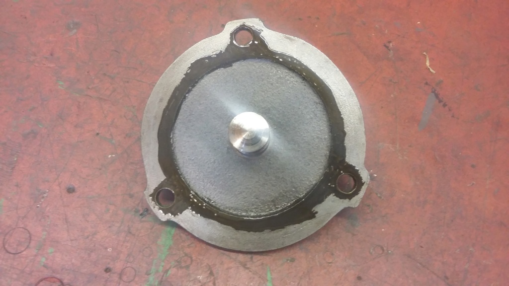
Gasket sealant applied just where the gasket will cover!
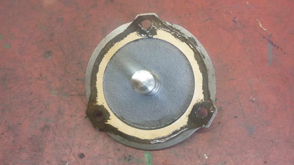
Gasket placed on housing, again with sealant applied only where the two items contact.
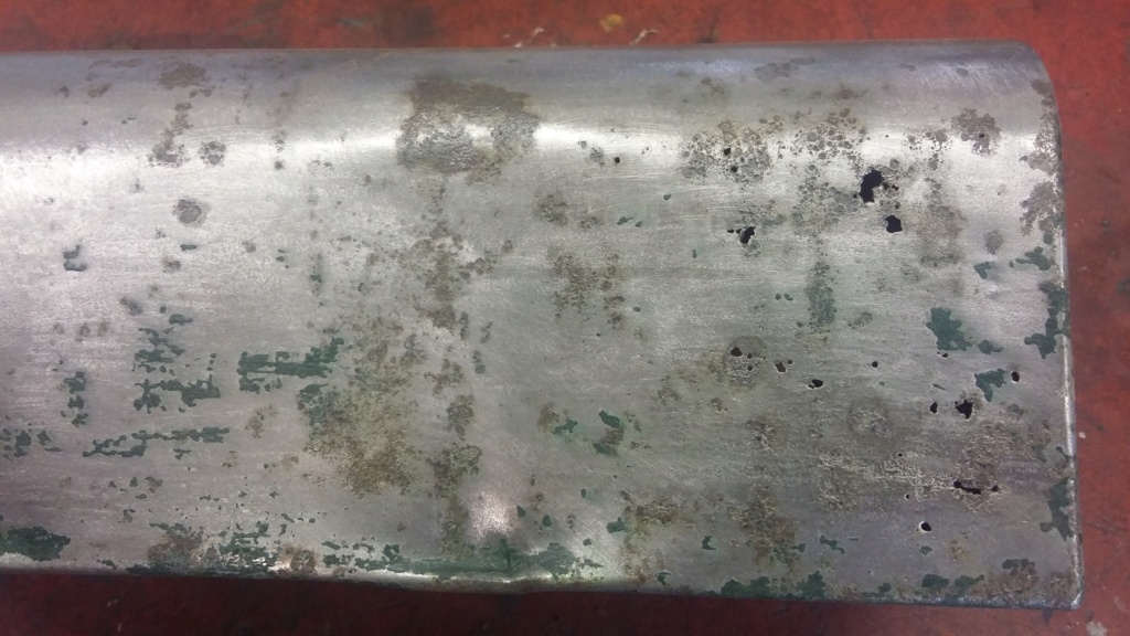
Fuel tank, exposing its lace curtain bottom!
Following on from my comments regarding the gasket for the governor housing, I decided that as it has been made and used as is for many years, I would give it a try. I assume it will work but it still doesn't make any sense to me.
The last main issue to overcome on the "D" is the fuel tank. The one I have, revealed a lace curtain base, once I had taken the paint off, even though I used chemical paint stripper, rather than wire wheeling to strip it. Looking at it I'm not sure it is repairable, by using any of the tank sealing products. If that proves to be the case, I will be in the market for a replacement tank. Up until I sort the tank out, all the test runs of the "D" have to be undertaken by topping up the carburettor bowl.
The test runs undertaken so far, have shown the engine to run quite well. However I have not been able to run it for very long, as it is in the garage with the exhaust pointing out of the door. Also I have not filled the water hopper so far, as I want to thoroughly warm the engine block up and then let it cool down completely, before taking the rocker shaft back out and nipping up all the head nuts again. Hopefully this will ensure the head is tightened down fully, preventing any leaks.

Gasket sealant applied just where the gasket will cover!

Gasket placed on housing, again with sealant applied only where the two items contact.

Fuel tank, exposing its lace curtain bottom!
neil (LE)- A credit to the forum

- Posts : 399
Join date : 2012-03-21
Age : 68
Location : N/W Kent
 Re: Lister H4 Pump Disassembly
A piece of thin steel sheet carefully soldered as a patch will be an easy and simple fix, use a soldering iron instead of a torch, nobody will see it underneath.
Maryalice
Maryalice
maryalice- Life Member

- Posts : 1310
Join date : 2010-01-23
Age : 70
Location : Bedfordshire
 Re: Lister H4 Pump Disassembly
Hi Martin, I might just try that, nothing to loose and I am fairly competent soldering and have a large bit, temperature controlled soldering station. A good clean up and plenty of flux, should see me alright. I'll let you know how it works out.
Neil
Neil
neil (LE)- A credit to the forum

- Posts : 399
Join date : 2012-03-21
Age : 68
Location : N/W Kent
 Re: Lister H4 Pump Disassembly
Hi, well I've taken the engine out of the garage, to allow for a longer test run with water in the jacket. I undertook the longer run after I had nipped all the head nuts up, once the engine was totally cooled down. To do this I had to remove the rocker shaft and the rockers and would like to have re-checked the valve clearance on reassembly. However I'm still not happy with the procedure of inserting the feelers, due to the location of the rockers. This makes getting straight feeler gauges in the correct position rather awkward and impossible without bending the feelers which makes an accurate measurement unlikely. I imagine I should be able to work it out from the thread pitch and turn back the adjuster the appropriate number of turns to equate to 31 thou, but I haven't done the maths yet!
When I did run the engine, I found that although it ran fairly well at a higher speed, it was rather fickle and would stutter and falter, if the speed was adjusted down whilst it was running. It also seemed to require a lot more cranking to start it, than had been necessary previous to the rebuild. I knew I had sufficient compression, the carburettor was clean, I had rechecked the ignition timing, which seemed spot on and the magneto drive chain was new and there was very little slack which might have caused erratic timing, so I was left thinking that the spark might be weak. I really didn't want to but I removed the mag again to check it out, which indicated that although there was a spark it wasn't strong. I hoped this didn't indicate an issue with the coil but I didn't think so. Instead I decided to change out the capacitor (condenser), as I had a new one available. That did the trick, once more I had a good strong spark, even at a slow rotational speed. Once fitted back onto the engine and re-timed, the engine started almost on the first turn of the handle and I was now able to get the engine to run consistently at a very slow speed, probably less than 100 rpm. I realise it is not good to run the engine too slowly for very long due to the splash lubrication but for relatively short periods I don't think it does any harm. Also for me, I feel it demonstrates that the fundamentals of the engine, such as compression, ignition timing, magneto, valve seating and the carburettor must be in good order, to allow the engine to operate at such a slow speed.
Once I was happy everything was working as it should, I finished off the day's work, by fitting the transfers to the engine hopper. You know you're nearly there, when the transfers are applied!
Although I still have the fuel tank issue to resolve, as I have not yet attempted to undertake a soldered patch repair, I have repaired the petrol pipe by soldering the end back on, I'm now very close to being able to at least attempt to belt the engine up to the pump. Even if this is just to see if the pump will turn over, with the Lister "D" providing the power. I hope to jury rig something in the next day or so, weather dependant, so watch this space.
The only other item I would like to get back on the engine, is the original Lucas RS 1 type magneto, which I had to change out for SR 1 type earlier on, to get the engine to run. I have taken the RS 1 mag apart and it is apparent that it has suffered with damp. The bearings are rusty and will need replacing which hopefully wouldn't be too difficult but I haven't yet been able to check the coil out but I fear it may be dead due to the damp. If it is, I might have to live with the SR 1 as a new coil could cost more than the value of the engine!
Neil.
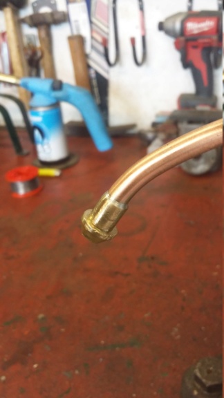
Fuel pipe end re-soldered.
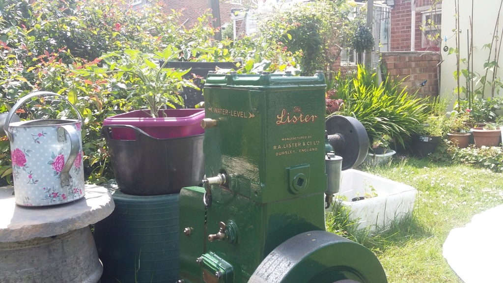
Hopper sporting a new set of transfers. You know you're nearly there when the transfers are applied.
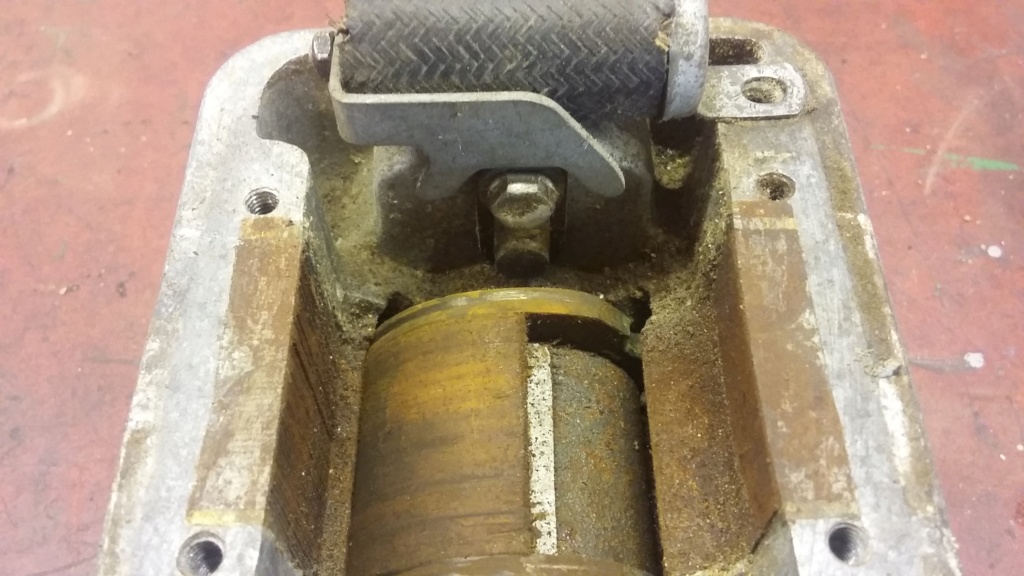
Overall condition of the original RS 1 magneto.
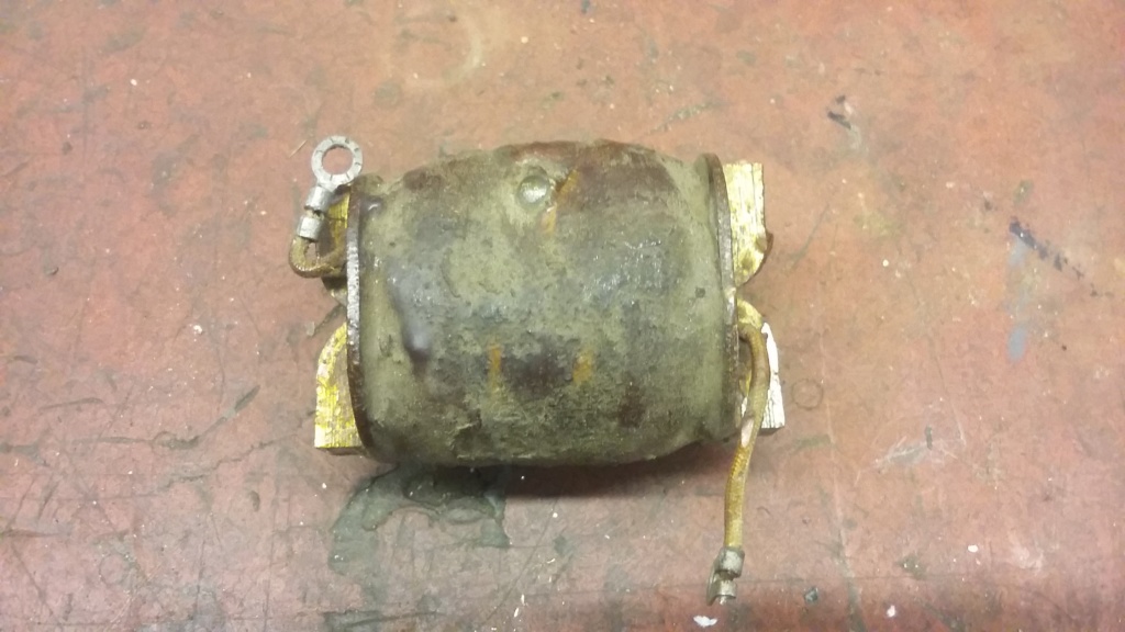
The suspect coil. I fear it may be dead.
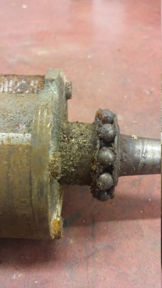
The rusty bearing, I think it will need to be replaced!
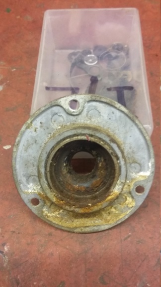
And the bearing cup.
When I did run the engine, I found that although it ran fairly well at a higher speed, it was rather fickle and would stutter and falter, if the speed was adjusted down whilst it was running. It also seemed to require a lot more cranking to start it, than had been necessary previous to the rebuild. I knew I had sufficient compression, the carburettor was clean, I had rechecked the ignition timing, which seemed spot on and the magneto drive chain was new and there was very little slack which might have caused erratic timing, so I was left thinking that the spark might be weak. I really didn't want to but I removed the mag again to check it out, which indicated that although there was a spark it wasn't strong. I hoped this didn't indicate an issue with the coil but I didn't think so. Instead I decided to change out the capacitor (condenser), as I had a new one available. That did the trick, once more I had a good strong spark, even at a slow rotational speed. Once fitted back onto the engine and re-timed, the engine started almost on the first turn of the handle and I was now able to get the engine to run consistently at a very slow speed, probably less than 100 rpm. I realise it is not good to run the engine too slowly for very long due to the splash lubrication but for relatively short periods I don't think it does any harm. Also for me, I feel it demonstrates that the fundamentals of the engine, such as compression, ignition timing, magneto, valve seating and the carburettor must be in good order, to allow the engine to operate at such a slow speed.
Once I was happy everything was working as it should, I finished off the day's work, by fitting the transfers to the engine hopper. You know you're nearly there, when the transfers are applied!
Although I still have the fuel tank issue to resolve, as I have not yet attempted to undertake a soldered patch repair, I have repaired the petrol pipe by soldering the end back on, I'm now very close to being able to at least attempt to belt the engine up to the pump. Even if this is just to see if the pump will turn over, with the Lister "D" providing the power. I hope to jury rig something in the next day or so, weather dependant, so watch this space.
The only other item I would like to get back on the engine, is the original Lucas RS 1 type magneto, which I had to change out for SR 1 type earlier on, to get the engine to run. I have taken the RS 1 mag apart and it is apparent that it has suffered with damp. The bearings are rusty and will need replacing which hopefully wouldn't be too difficult but I haven't yet been able to check the coil out but I fear it may be dead due to the damp. If it is, I might have to live with the SR 1 as a new coil could cost more than the value of the engine!
Neil.

Fuel pipe end re-soldered.

Hopper sporting a new set of transfers. You know you're nearly there when the transfers are applied.

Overall condition of the original RS 1 magneto.

The suspect coil. I fear it may be dead.

The rusty bearing, I think it will need to be replaced!

And the bearing cup.
neil (LE)- A credit to the forum

- Posts : 399
Join date : 2012-03-21
Age : 68
Location : N/W Kent
Page 5 of 6 •  1, 2, 3, 4, 5, 6
 Similar topics
» Lister 'd' to lister domestic pump
» Lister H1 pump nut
» Lister Domestic Pump
» Lister domestic pump help ....
» Lister H3 pump
» Lister H1 pump nut
» Lister Domestic Pump
» Lister domestic pump help ....
» Lister H3 pump
Page 5 of 6
Permissions in this forum:
You cannot reply to topics in this forum
