
WW2 US Army Homelite Generating Set
Page 2 of 5 •  1, 2, 3, 4, 5
 ![]()
Re: WW2 US Army Homelite Generating Set
![]() by pauldg Fri Aug 03 2012, 17:31
by pauldg Fri Aug 03 2012, 17:31
If that bearing with the groove in is only held in one direction - i.e. it's a stepped housing, then get a bearing the same width as the part up to the groove and use a spacer (a couple of washers...
pauldg- A credit to the forum

- Posts : 300
Join date : 2012-06-30
Age : 47
Location : South Wiltshire
Re: WW2 US Army Homelite Generating Set
![]() by Ianhw77k Fri Aug 03 2012, 20:13
by Ianhw77k Fri Aug 03 2012, 20:13
Grab that folding workbench and any other interesting bits while you are there pleasenutgone wrote: which should give me time to empty her shed out & see what I can turn up.
(Actually I can see myself getting roped into helping

Ianhw77k- A credit to the forum
- Posts : 455
Join date : 2012-07-02
Age : 45
Location : East Sussex
Re: WW2 US Army Homelite Generating Set
![]() by nutgone Fri Aug 03 2012, 23:09
by nutgone Fri Aug 03 2012, 23:09
Ianhw77k wrote:Grab that folding workbench and any other interesting bits while you are there pleasenutgone wrote: which should give me time to empty her shed out & see what I can turn up.
(Actually I can see myself getting roped into helping)
Took the words right out of my mouth!
See you there Sunday!
_________________
The "F" key is dying on my computer, please remember this when reading my posts, I'm trying to avoid using it.
The name's Matt, but call me Nutts if you like, there's already enough Matt's about.

nutgone- Life Member
- Posts : 2356
Join date : 2012-07-04
Age : 45
Location : East Sussex
Re: WW2 US Army Homelite Generating Set
![]() by nutgone Fri Aug 03 2012, 23:18
by nutgone Fri Aug 03 2012, 23:18
I did a bit more cleaning today & had a better look at the genny side of things. I've made up a rough diagram of it all, if only to remember where everything goes. I've also been taking readings from the coils & the DC armature. The readings look promising so far, except some of the field coil readings on the DC side. I've taken some more pics & will post up my findings in my next post, either tomorrow or over the weekend. & I'll try to make up a half decent diagram of what I've found so far.
Ian, don't forget we're probably going to need to get that out-house door open again, I will need some help with that (I know the voltage regulator is in there).
Last edited by nutgone on Sat Aug 04 2012, 11:16; edited 1 time in total
_________________
The "F" key is dying on my computer, please remember this when reading my posts, I'm trying to avoid using it.
The name's Matt, but call me Nutts if you like, there's already enough Matt's about.
nutgone- Life Member
- Posts : 2356
Join date : 2012-07-04
Age : 45
Location : East Sussex
Re: WW2 US Army Homelite Generating Set
![]() by matt86 Fri Aug 03 2012, 23:29
by matt86 Fri Aug 03 2012, 23:29
good luck
matt

matt86- Admin
- Posts : 5577
Join date : 2011-03-29
Age : 38
Location : swindon/ faringdon
Re: WW2 US Army Homelite Generating Set
![]() by Ianhw77k Sat Aug 04 2012, 10:15
by Ianhw77k Sat Aug 04 2012, 10:15
nutgone wrote:
Ian, don't forget we're probably going to need to get that out-house door open again, I will need some help with that (I know the voltage regulator is in there).
Not sure about Sunday now, might be having an at home day as we might be having the out-laws over for dinner. I'll have to see how today goes.
Ianhw77k- A credit to the forum
- Posts : 455
Join date : 2012-07-02
Age : 45
Location : East Sussex
Re: WW2 US Army Homelite Generating Set
![]() by nutgone Sat Aug 04 2012, 12:17
by nutgone Sat Aug 04 2012, 12:17
On the AC end, there are 2 main sets of windings, 1 each side, which look like this....
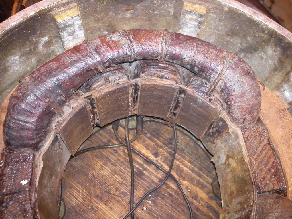
Each of these sets of windings has 4 smaller coils inside one larger coil. Each of the smaller coils appears to be of quite thick wire though....
There are just 4 wires coming out of this part of the generator, 2 appear to be thicker & 2 thinner. I have tested for resistance between these wires & I'm getting readings between all of them, some are higher readings (greater resistance) some are lower. There is also a very high resistance between these wires & the metal chassis of the genny (earth). Perhaps I should have actually written down these readings & posted them as well.
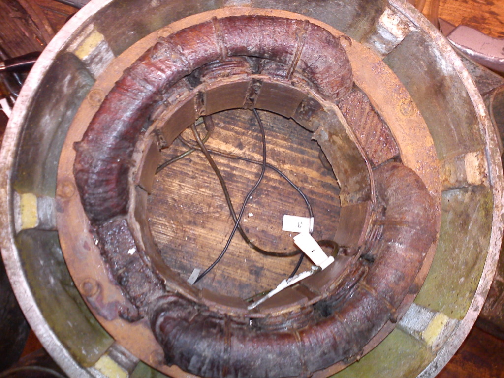
Now to the DC side of things. There are 4 field windings here, like so....

Each of these 4 windings has 2 sets of coils on it. There is a much smaller gauge of wire on the inner (closest to the laminated core) & a much thicker coil wrapped around the outside of this. I recently discovered both coils are in fact of enamelled copper wire....
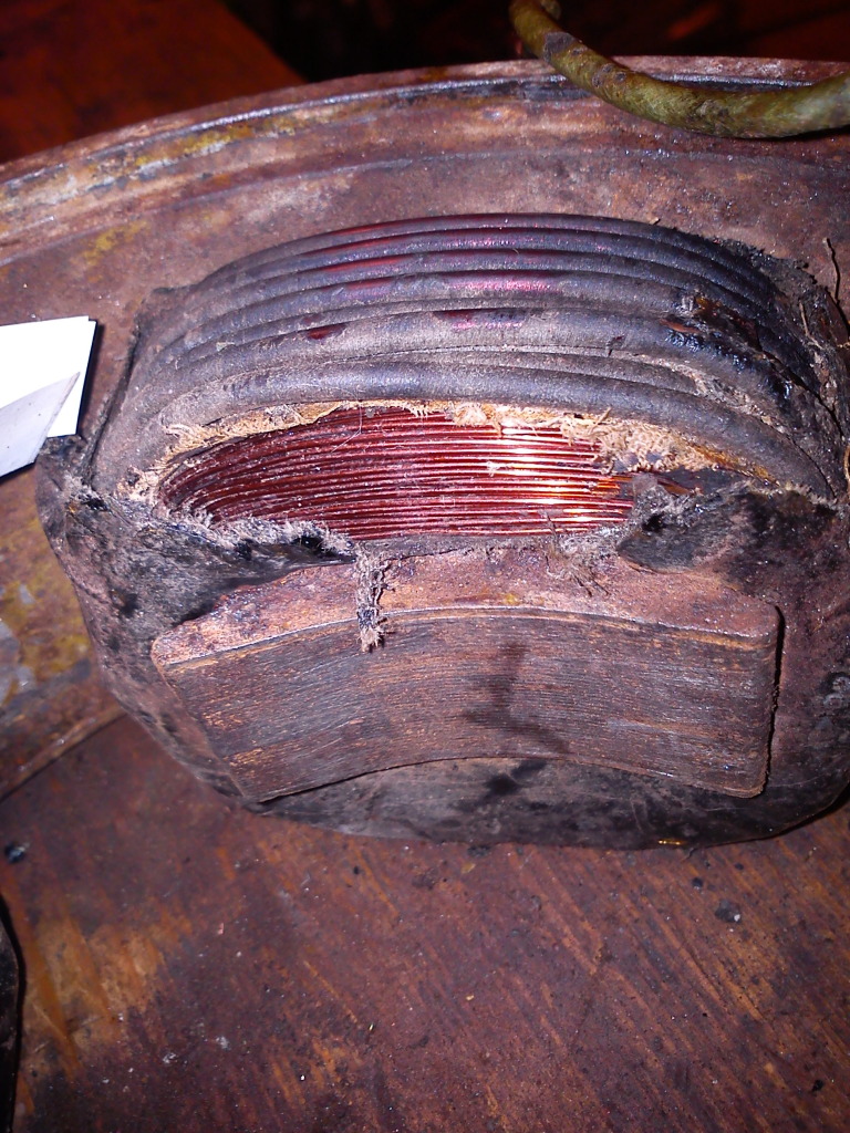
These thinner & thicker windings have a layer of something (looks like impregnated canvas) between the 2 different thickness windings.
These coils are joined together, leaving 4 wires to terminate, 2 thin & 2 thick. I have measured resistances here as well, I was expecting low resistance on the thick 2 & slightly higher on the thinner 2 (which I got), but I'm also getting readings between all the wires, which I wasn't expecting, but then I don't know how they are wired together, I haven't separated any of these coils from eachother, but it looks like only thick wires are joined to thick, & only thin to thin, but I could be mistaken.
I also got very high readings here back to the metal chassis (earth), but these weren't as high as on the AC side.
There are 4 brushes on the DC generator, these are linked together in pairs, each pair has a capacitor connected to it (I assume for interference suppression). The thin & thick field coils are joined on one of these brushes, the other brush only takes a thin wire, the other thick one runs back to the terminal block. One of these brushes (I think the one with just the thin field wire on it) is connected (via the terminal block) to one of the AC generator wires.
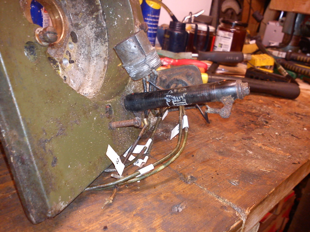
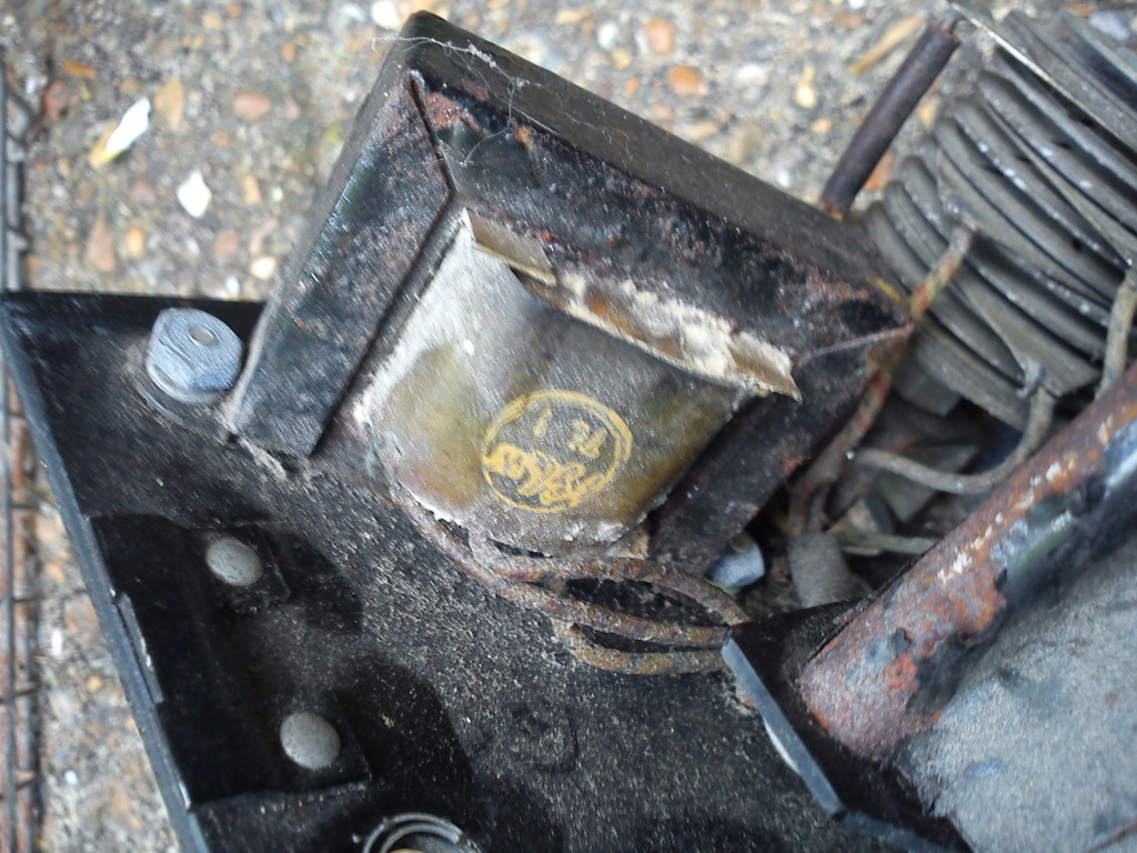
As for the terminations of all these wires, that's where things get more complicated. On the back of the genny we have the control/output section....
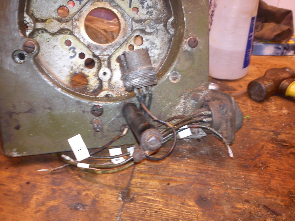
I have removed the 6 terminal block from the back here for cleaning, but I have labelled up all the wires, taken pictures & drawn a couple of diagrams to tell me where everything goes.
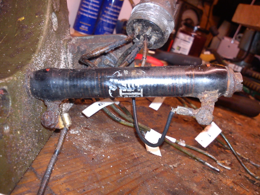
Basically, on the back here we have a 4 pin aircraft plug (loose), an 8 pin aircraft socket (fixed) & a long black thing (fixed), which I reckon is a resistor. Have a closer look here, The 4 pin plug goes to the voltage regulator (which I still have), it has 2 wires in & 2 wires out. The 8 pin socket is for the output, but only uses 7 (I think) of it's pins (might even be just 6). I've tested the long black thing, & it reads around 3.1 Ohms.....
I've also tested between the commutator strips on the armature, & I get readings (quite low readings) between all the strips. I have no idea if this is normal.
I will make up a better diagram of how everything is wired up & post it at some stage. Basically:-
The voltage regulator takes one wire from the AC bit & one from the DC bit (which I thought was a bit strange, but makes sense when you think about it, I suppose), one of these wires runs through that resistor thingy first though.
There is a 6 terminal block, but only 5 of the terminals are actually used.
There are no slip rings for the AC generator (which the genny-knowledgeable folk will know anyway, from looking at the rotor).
All these terminals go to the main output socket. By that I mean both regulated & unregulated outputs from both sides.
Anyway, I'll leave it at that for now, until I can get this diagram sorted. I will write down my resistance readings & include them on the diagram.
_________________
The "F" key is dying on my computer, please remember this when reading my posts, I'm trying to avoid using it.
The name's Matt, but call me Nutts if you like, there's already enough Matt's about.
nutgone- Life Member
- Posts : 2356
Join date : 2012-07-04
Age : 45
Location : East Sussex
Re: WW2 US Army Homelite Generating Set
![]() by nutgone Sat Aug 04 2012, 20:25
by nutgone Sat Aug 04 2012, 20:25

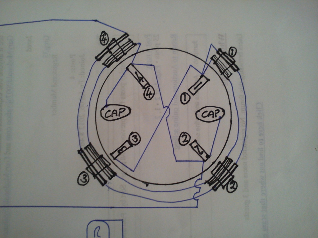
I've shown the AC side just as a box, as there's no way to tell which wires go where (2 are thinner & 2 are thicker though, but I'll get to that), these wires are numbered 1, 2, 3 & 5 from the terminals they end up in, in the terminal block.
Also shown is the big resistor thingy & the 4 pin plug which goes into the voltage regulator. I will photograph the regulator when I eventually get it out of my sister's outhouse.
The big circular thing on the right is the DC end with the brushes etc, I've drawn this in black in the hopes of making it a bit clearer. I've tried to show the different field coils (around the outside) & how I think they are connected together, the thicker wire coils are the outer ones (which should be apparent).
I've also labelled the capacitors "CAP" & numbered the brushes (inner most in the circle, the small rectangles) from 1 to 4, the numbers on the coils just correspond to which brush they sit under, they don't really mean much & none of these numbers correspond to the other numbers in the diagram (I should've labelled the brushes & coils A, B, C & D really). Here's a close up of it....
I've taken some resistance measurements of the various coils, here's what I've found....
AC generator wires:
Wire 1 to Wire 2 = 0.1 Ohm
Wire 3 to Wire 5 = 4.1 Ohm
All other wires were open circuit, none are connected to earth either.
Wires 1 & 2 are also thicker (I think) than wires 3 & 5. Either way, there are 2 thinner ones & 2 thicker ones & they pair up with the readings.
This seems to show that there is a low resistance coil between wires 1 & 2, which I guess is the AC output (what I call "pick-up") coil(s). There is a higher resistance coil between wires 3 & 5 (there is no 4) which, if you follow things on the diagram, appears to be the DC excitation coil(s).
DC generator Coils:
Thick wire to thick wire = 0.0-0.1 Ohm
Thin wire to thin wire = 17.9-18.0 Ohms
Thin to thick was open circuit, all coils to earth was also open circuit
I don't have much clue what this means, except that my readings last night were obviously wrong, I think I was reading high resistances through moisture in the coils from all the cleaning fluid I had been using. After being allowed to dry over night things seemed a lot better.
This seems to be good news. I still don't know why the DC generator has these different coils, they may be something to do with starting, or some other reason, but the readings look good.
The AC side must be a single phase winding of some sort, I'm not sure. I thought AC generators were wired in a star formation, but this looks different. Might have something to do with the 400 cycles per second, I dunno.
I think I'm happy with this though. If I tried really hard I could get some cross coil readings in the MegOhm ranges, but really they can be considered open circuit. I would like to know exactly what's going on in there though. I've started to try & draw up some schematic diagrams of the different coils & how they are connected, so I'll know where to draw power from, once it's running.
Also, if this shows the genny is good, I will get the engine running weather or not I can find the petrol tank. If the tank is no more I will fabricate something else with a gravity feed tank & a normal carb. I'm sure I can make it look OK.
_________________
The "F" key is dying on my computer, please remember this when reading my posts, I'm trying to avoid using it.
The name's Matt, but call me Nutts if you like, there's already enough Matt's about.
nutgone- Life Member
- Posts : 2356
Join date : 2012-07-04
Age : 45
Location : East Sussex
Re: WW2 US Army Homelite Generating Set
![]() by pauldg Sun Aug 05 2012, 02:31
by pauldg Sun Aug 05 2012, 02:31
The fixed coils 'look' almost like they should be the other way round - the set of 4 would make sense to be the AC if they were wired differently. But that said - the homelite generators seemed to be available in all sorts of frequency options. 180Hz was pretty popular from what I saw.
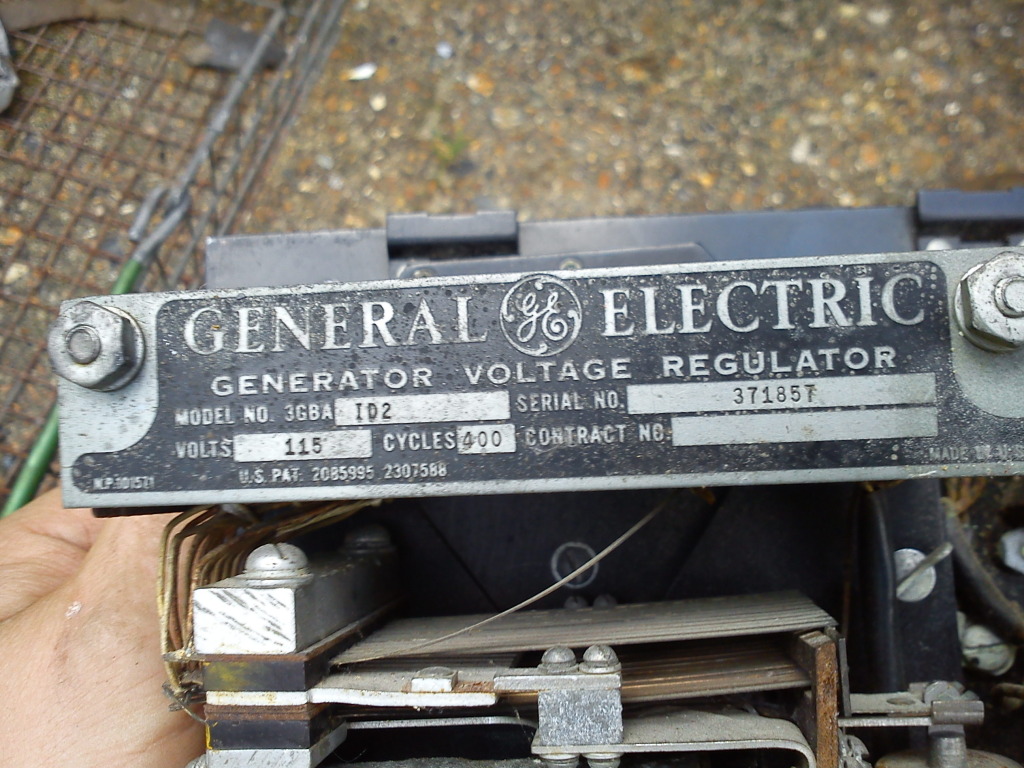
Has this one got a frequency/voltage plate?
It's certainly going to take a little thinking!
(btw, I found some images of the underslung pressure fed tanks - but I also found that a standard carb was fitted to certain models with the same power plant, so either way it should work out ok.)
pauldg- A credit to the forum
- Posts : 300
Join date : 2012-06-30
Age : 47
Location : South Wiltshire
Re: WW2 US Army Homelite Generating Set
![]() by nutgone Sun Aug 05 2012, 12:46
by nutgone Sun Aug 05 2012, 12:46
It looks like I've got it all round the right way. Someone on SmokStak reckons there should be slip rings on AC gennys, he said he reckons someone has taken bits off this one, but I don't think he knows these sets (I think he was just replying to my thread because no one else has).
I'm guessing the DC side all looks fine (except the weird thin & thick coils), but the AC side looks a bit unorthodox. Like I said, most AC gennys are star formation windings, this thing appears to have just 2 coils in the stator & just a laminated core for the rotor. I'm only guessing which coils do what from the connection diagram I drew up.
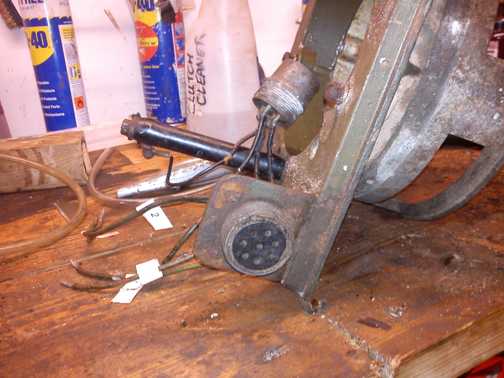
The output socket looks to me like (from bottom to top) 2 AC outputs (regulated via their DC field coils), 2 unregulated DC outputs, then 2 regulated DC outputs.
The regulator is another oddity, it's a fair old lump. It's locked in an old outside loo here at my sister's place, something has dropped down from the pile of stuff in there & blocked the door shut tight, so someone's got to try & get in there, probably through the tiny window.
Once it's out I'll get some pics, but for now I don't think it's that important, as there's only 4 wires going to it.
As for the rest of it, I reckon I'll get it going again. That mag looks OK, I think I tested the coil, so it'll have a spark. If it has to have a normal carb & gravity feed tank then so be it, at least it'll be running. (I'm really looking forward to it now. I don't think this engine has been run much, by the looks of it).
_________________
The "F" key is dying on my computer, please remember this when reading my posts, I'm trying to avoid using it.
The name's Matt, but call me Nutts if you like, there's already enough Matt's about.
nutgone- Life Member
- Posts : 2356
Join date : 2012-07-04
Age : 45
Location : East Sussex
Re: WW2 US Army Homelite Generating Set
![]() by pauldg Sun Aug 05 2012, 15:29
by pauldg Sun Aug 05 2012, 15:29
I agree that usually an AC generator would have sliprings, but it depends on the design - in the 'using motor as generator' thing those don't have have any and still make electricity - you just need some way to excite it (and showing it pictures of another generator with the casing off probably won't work
As for the formation of the windings, that also depends on the amount of phases you're dealing with.
pauldg- A credit to the forum
- Posts : 300
Join date : 2012-06-30
Age : 47
Location : South Wiltshire
Re: WW2 US Army Homelite Generating Set
![]() by nutgone Sun Aug 05 2012, 16:55
by nutgone Sun Aug 05 2012, 16:55
pauldg wrote:Hertz is cycles per second, so that 400 cycles is 400Hz.
That's what I thought, but when I was studying some Donald Smith devices, there was talk of each cycle having 2 peaks, so when using a Nomograph (think that's what it's called) to calculate sizes of capacitors or resistors, for the American 60Hz you need to use the 120Hz line, which was why I wondered about the use of "Cycles" instead of simply putting Hertz (or was Hertz, the scientist, a German? Maybe that's why they put "Cycles" instead, this was WW2 after all).
Anyway, never mind all that, I've got some news........
_________________
The "F" key is dying on my computer, please remember this when reading my posts, I'm trying to avoid using it.
The name's Matt, but call me Nutts if you like, there's already enough Matt's about.
nutgone- Life Member
- Posts : 2356
Join date : 2012-07-04
Age : 45
Location : East Sussex
Re: WW2 US Army Homelite Generating Set
![]() by nutgone Sun Aug 05 2012, 17:18
by nutgone Sun Aug 05 2012, 17:18
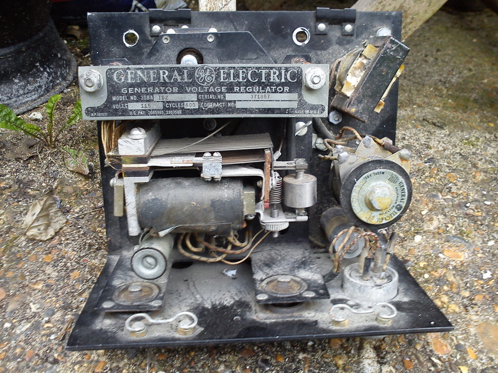
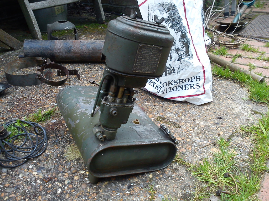
That's the rather complicated voltage regulator. In the same place I found a few more bits & bobs....
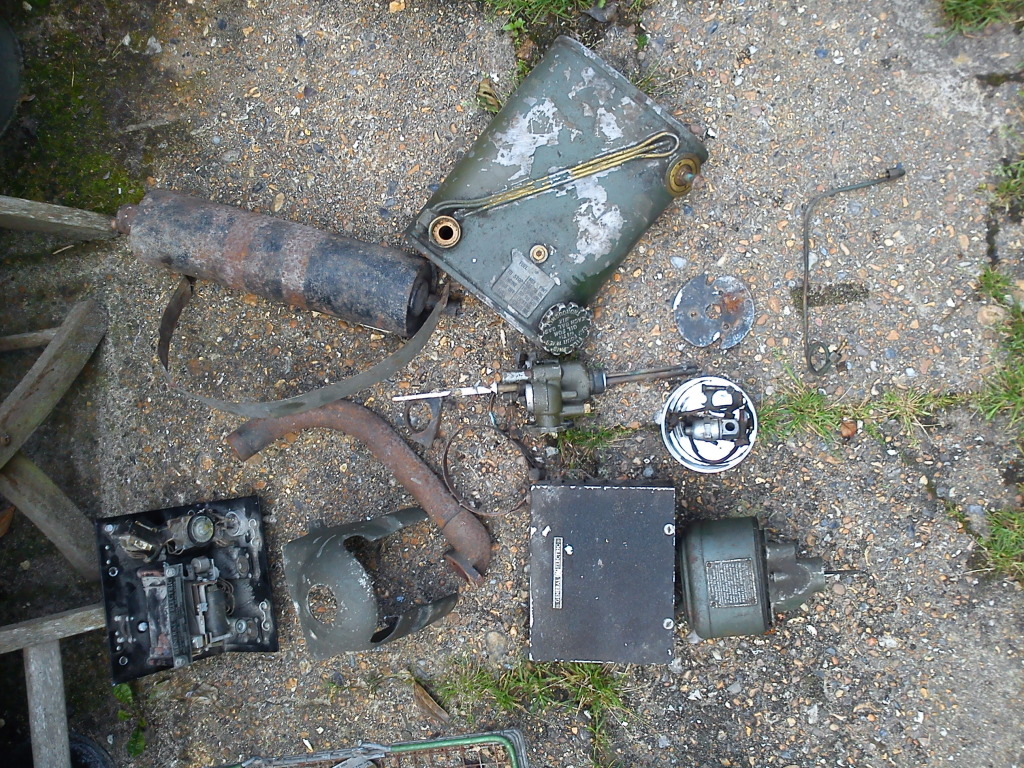
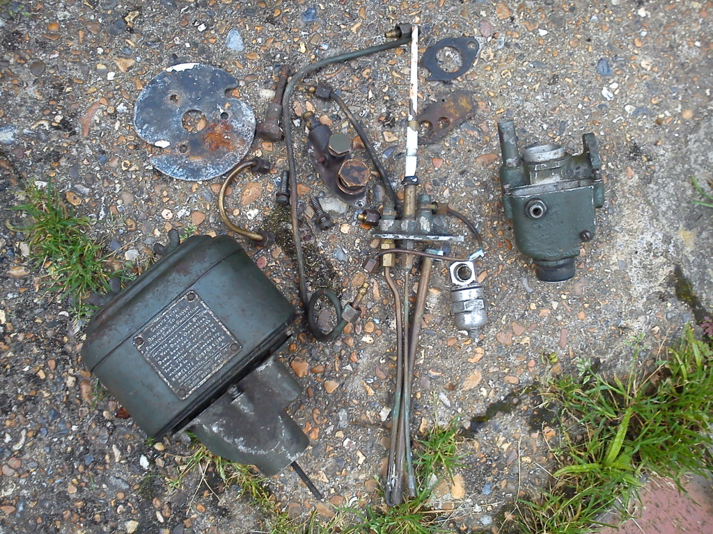
Here we have the fuel tank....

The bits of the carb....
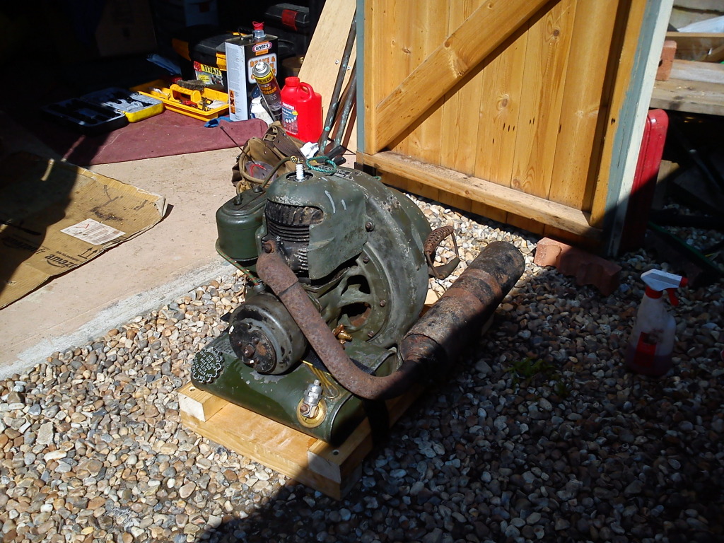
& some odd bits of cowling, the exhaust pipe, silencer & some odd straps....

From memory I can say what's missing; the mounting skids (which I knew I didn't have) & a big green tin box which sits over the voltage regulator & output connections. The fuel tank will also need some straps, but they were disintegrated years ago.
I've started piecing bits together from memory....
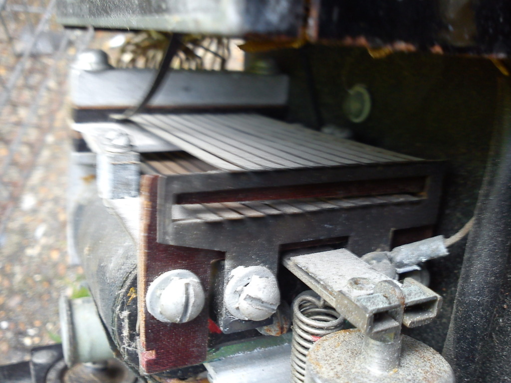
I've also taken some close-up pics of the voltage regulator. This is the biggest bit of the assembly....
It has what looks like 2 large magnetic coils underneath, which lift lots of little copper (or brass) strips....
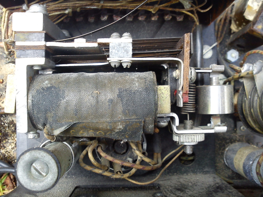
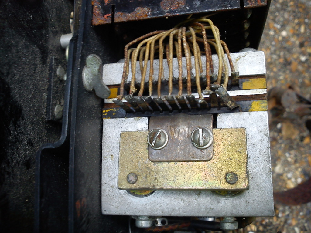
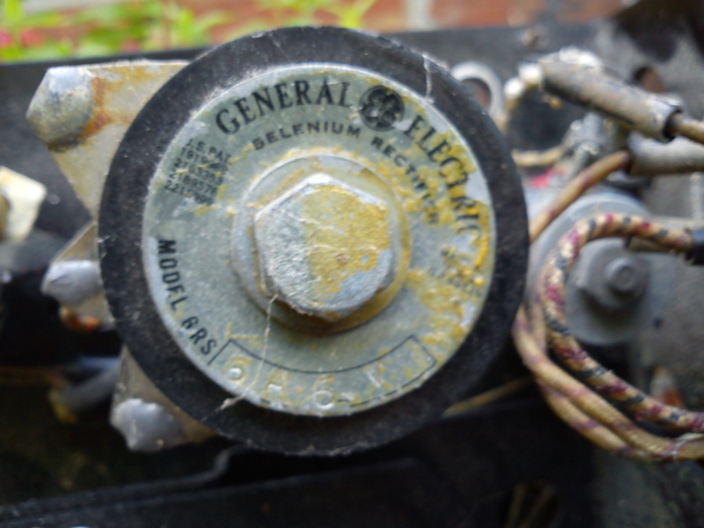
It also has a Selenium Rectifier....
What looks like a pre-set variable resistor (variable coil) which sits under the big regulator....
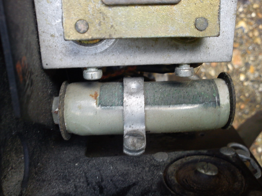
Another cylindrical piece (not sure what it is)....
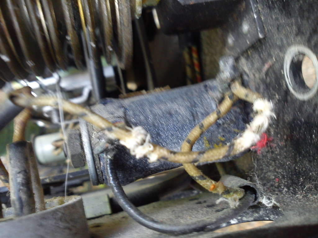
& perhaps strangest of all, it seems to have a small transformer, which I thought were meant for AC, but I thought this regulator worked on the DC exciter coils....
_________________
The "F" key is dying on my computer, please remember this when reading my posts, I'm trying to avoid using it.
The name's Matt, but call me Nutts if you like, there's already enough Matt's about.
nutgone- Life Member
- Posts : 2356
Join date : 2012-07-04
Age : 45
Location : East Sussex
Re: WW2 US Army Homelite Generating Set
![]() by pauldg Sun Aug 05 2012, 18:31
by pauldg Sun Aug 05 2012, 18:31
It has a rectifier.
It has that transformer (although this could be a choke - not sure yet).
On the data plate (the same plate that says regulator) it says 'cycles 400'.
A DC generator should have no need of rectification, that's what the multi-contact comm is for. But you do need to rectify AC to give an excitation voltage to the AC field coils.
Is there anything to say what rpm the engine should operate at?
(That variable wire-wound is the same sort of thing I need for my generator...
pauldg- A credit to the forum
- Posts : 300
Join date : 2012-06-30
Age : 47
Location : South Wiltshire
Re: WW2 US Army Homelite Generating Set
![]() by matt86 Sun Aug 05 2012, 18:36
by matt86 Sun Aug 05 2012, 18:36
matt
matt86- Admin
- Posts : 5577
Join date : 2011-03-29
Age : 38
Location : swindon/ faringdon
Re: WW2 US Army Homelite Generating Set
![]() by Ianhw77k Sun Aug 05 2012, 19:24
by Ianhw77k Sun Aug 05 2012, 19:24
I know what you mean mate, even a magneto seems like black magic to mematt86 wrote:all this generating / electroc jargen is going beyond me .......through's away the multimeter and give me a spanner anyday

matt
Ianhw77k- A credit to the forum
- Posts : 455
Join date : 2012-07-02
Age : 45
Location : East Sussex
Re: WW2 US Army Homelite Generating Set
![]() by nutgone Sun Aug 05 2012, 20:03
by nutgone Sun Aug 05 2012, 20:03
The long pipes (there's 3 of them together there) sit in a small reservoir in the bottom of the tank, one is connected to the disc valve, & I think it uses crank case pressure to pull fuel up another of the 3 pipes by venturi action into a small bit in the main carb body, which I can only describe as a shelf, this acts like the float chamber in a normal carb, it has an adjustable needle jet, like a normal carb.
Which all sounds great, but then there's 2 other pipes I can't work out, there's another one, connected via 2 ball valves & a small tube to the intake ports, this has it's own tube which reaches down into the tank (one of the 3 I mentioned earlier, which sit in the reservoir bit), I can only think this is some kind of petrol injection thingy, directly into the intake ports in the cylinder
Then there's the petrol tap! This is a through-tank fitting, it has another small pipe on the bottom of the tank, which supplies fuel to the little reservoir bit I mentioned earlier.
Then there's a small tap on the bottom of the crank case, this seems to be joined, by yet another little pipe, to a part of the petrol tank which I have no idea about, I think there's some kind of float in there or something, this is then (I think) connected by some pipes (which are soldered to the outside of the tank) to the top end of that little reservoir thingy!!!
I've had it all to bits & it's one of those things, just when you think you've worked it all out you spot another pipe going somewhere which you just can't figure out!
I think I'll just have to clean out all the little pipes, put it together & hope it starts!
I've got some work to do before then though.
Oh yeah, take another look at that pic, see the white bit sticking out of part of the carb??? This bit sticks through the air filter, I think it just locates it.
Wanna know why it's white?
Some tosser has used it to stir a pot of paint!
Last edited by nutgone on Sun Aug 05 2012, 20:26; edited 2 times in total
_________________
The "F" key is dying on my computer, please remember this when reading my posts, I'm trying to avoid using it.
The name's Matt, but call me Nutts if you like, there's already enough Matt's about.
nutgone- Life Member
- Posts : 2356
Join date : 2012-07-04
Age : 45
Location : East Sussex
Re: WW2 US Army Homelite Generating Set
![]() by nutgone Sun Aug 05 2012, 20:18
by nutgone Sun Aug 05 2012, 20:18
Looking at my earlier (excuse for a) wiring diagram it looks like it's the DC that's fed into the regulator, & then on into the AC generator's field windings, but I'm probably wrong on that now, looking at the regulator.
There may have been a link between certain pins on the outlet plug, I wouldn't know as I only have the outlet socket, obviously the plug would be on the Aeroplane or Tank or whatever this thing ran.
Would like to work it out though, as I would like to actually use it. The 27v DC is obviously battery charging voltage for 24v batteries, so I could in theory use that, the 115v AC could be used to light up some 110v site bulbs, like I do with the Tarpen.
As for engine speed, someone told me it was 3000 RPM, but I couldn't tell you for sure, there's nothing marked on the engine that I can see. I was hoping to work it out from the 6 arms on the AC rotor & the 2 sets of 4 coils on the AC stator, but for all I know the stator coils I'm looking at, thinking they are "pick-up" coils could be the excitation coils!
BTW, that large piece labelled "Generator Voltage Regulator" actually comes off the rest of the panel, leaving the rectifier, transformer/choke thingy & the other cylindrical thing, which I now know is a large resistor. The pre-set variable coil goes with the regulator part.
The regulator part, when separated, reveals a fixed 8 pin plug & socket (only 6 pins used) which looks like an old radio-valve socket. I'll take some pics of this when I get to it next (I've locked it all in my car, ready to take home in the next few days).
_________________
The "F" key is dying on my computer, please remember this when reading my posts, I'm trying to avoid using it.
The name's Matt, but call me Nutts if you like, there's already enough Matt's about.
nutgone- Life Member
- Posts : 2356
Join date : 2012-07-04
Age : 45
Location : East Sussex
Re: WW2 US Army Homelite Generating Set
![]() by pauldg Sun Aug 05 2012, 22:37
by pauldg Sun Aug 05 2012, 22:37
To be honest, without a full wiring diagram I can't see a whole lot!! Well, that or actually getting my grubby mitts on it...
I'll have another look though at the pics and the diagram you've done - never know, maybe some sort of inspiration will strike me.
Of course, you could just stick it all back together how it was and see if any electricity dribbles out anywhere
pauldg- A credit to the forum
- Posts : 300
Join date : 2012-06-30
Age : 47
Location : South Wiltshire
Re: WW2 US Army Homelite Generating Set
![]() by nutgone Sun Aug 05 2012, 23:11
by nutgone Sun Aug 05 2012, 23:11
pauldg wrote:
Of course, you could just stick it all back together how it was and see if any electricity dribbles out anywhere
I think that's what's going to happen with this one. I've got a feeling it'll probably give out DC without much effort, but maybe AC needs it to be plugged into something. Something with the right bits on the end of the lead.
I'll see what I can do about some sort of wiring diagram, but can't promise anything. I'm not getting many bites on SmokStak with this stuff.
_________________
The "F" key is dying on my computer, please remember this when reading my posts, I'm trying to avoid using it.
The name's Matt, but call me Nutts if you like, there's already enough Matt's about.
nutgone- Life Member
- Posts : 2356
Join date : 2012-07-04
Age : 45
Location : East Sussex
Re: WW2 US Army Homelite Generating Set
![]() by pauldg Sun Aug 05 2012, 23:25
by pauldg Sun Aug 05 2012, 23:25
Never know, I might get my head around what it's supposed to do sometime.
pauldg- A credit to the forum
- Posts : 300
Join date : 2012-06-30
Age : 47
Location : South Wiltshire
Re: WW2 US Army Homelite Generating Set
![]() by nutgone Mon Aug 06 2012, 22:37
by nutgone Mon Aug 06 2012, 22:37
However, this information only goes back to the Vietnam War era, & although I expect this genny may have still been in circulation around that time, as it dates from 1944 I can't be sure this still rings true.
Basically they standardised all their gennys in the late 1960s so they all had code numbers starting with the letters MEP (mobile electric power), this was done to make maintenance & spares supply easier.
It looks like the 400Hz is for radar systems, it's still in use today. Some construction gennys also used it for concrete vibrators & a few other tools, I'm guessing this was more to do with using up ex-MOD stock, rather than anything to do with the specifics of 400Hz supplies.
But still, I can't seem to make 400Hz divide into 3600rpm......
Or can I???
Been reading about it on this thread....
http://www.smokstak.com/forum/showthread.php?t=108154
_________________
The "F" key is dying on my computer, please remember this when reading my posts, I'm trying to avoid using it.
The name's Matt, but call me Nutts if you like, there's already enough Matt's about.
nutgone- Life Member
- Posts : 2356
Join date : 2012-07-04
Age : 45
Location : East Sussex
Re: WW2 US Army Homelite Generating Set
![]() by nutgone Thu Aug 09 2012, 22:45
by nutgone Thu Aug 09 2012, 22:45
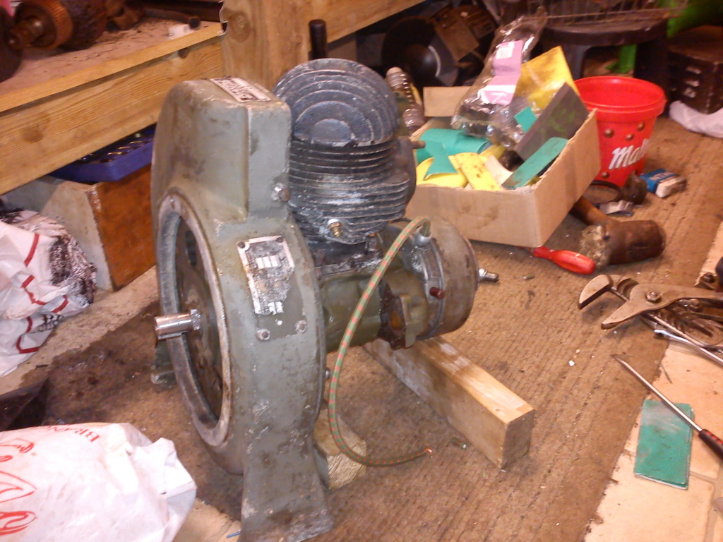
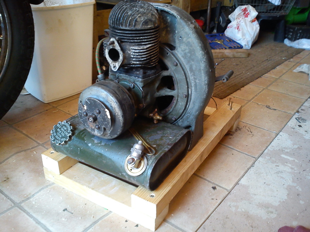
As you can see, she's taking shape. There appears to be a spark there as well, compression is really good, I just need to bolt the outer part of the genny back on to balance up the weight a bit & temporarily mount it onto 2 bits of wood, so I've got somewhere to put the fuel tank. Then I reckon we'll be ready to see if she runs.
Not sure what I've got planned for tomorrow, but if all goes well I should be able to devote most of the day to it. Now I've said that I bet something else will crop up, but still, we're well ahead of schedule.
there's loads more pics on the album now, as well.... http://photobucket.com/nutgonesyankgenny I've cleaned the fuel tank, cleaned the carb, it just wants putting together.
I'm not sure how long the bearings will last, or if I got them all in properly, but it all seems to turn OK. Guess we'll find out, won't we?
_________________
The "F" key is dying on my computer, please remember this when reading my posts, I'm trying to avoid using it.
The name's Matt, but call me Nutts if you like, there's already enough Matt's about.
nutgone- Life Member
- Posts : 2356
Join date : 2012-07-04
Age : 45
Location : East Sussex
Re: WW2 US Army Homelite Generating Set
![]() by Guest Fri Aug 10 2012, 12:00
by Guest Fri Aug 10 2012, 12:00
Stu.
Guest- Guest
Re: WW2 US Army Homelite Generating Set
![]() by nutgone Fri Aug 10 2012, 22:46
by nutgone Fri Aug 10 2012, 22:46
I've managed to get it started, but she won't run for more than about 30-60 seconds at a time. I can keep it running if I carry on pumping the primer pump, but I haven't told you about the primer pump yet, so I won't go into that just now.
Anyway, it's just a case of a little fuel starvation, my brother turned up & put a little more juice in the tank for me, I checked out all the different pipes, & we managed to get it to start & run a little longer, but it still stopped.
I've got a feeling I know roughly where the problem lies, but it'll need more tinkering. Well, they can't all be as easy as the Tarpen, can they?
I'm just pleased to know it starts, & I'm sure it will run, eventually. Actually, to say I'm pleased is a major understatement, I'm like a dog with 2 tails!
I will follow this up with a complete, technical description of the rebuild & some bits about the systems, & what I've discovered. I now fully understand how this whole thing works, even the genny side of things.
I've also done a little digging & have found out what these sets were used for. There's a reason I couldn't find this exact one on normal air force & army APU (aux. power unit) searches. To put it very briefly they were used to power the ground based mobile transmitter units for the SHORAN navigation systems, pioneered in Italy during WW2 & used during the Korean war. Here's a link to the forum where I found the information....
http://forum.armyairforces.com/1944-Homelite-PU4CPN2-Generator-info-needed-m223938.aspx
It's interesting stuff, I'm not sure if they were used for anything else, but it looks doubtful. It would seem these sets were designed specifically for this purpose & this purpose only. Obviously the engines & much of the general bits & bobs were used elsewhere, but these specific sets appear to be designed just for this purpose.
Anyway, I'm working my way through a bottle of red wine, as a little celebratory drink for getting her going. Next step is to carry on restoring the genny bits & get all that back together, see if it turns out any power.
_________________
The "F" key is dying on my computer, please remember this when reading my posts, I'm trying to avoid using it.
The name's Matt, but call me Nutts if you like, there's already enough Matt's about.
nutgone- Life Member
- Posts : 2356
Join date : 2012-07-04
Age : 45
Location : East Sussex
Page 2 of 5 • 1, 2, 3, 4, 5 ![]()
» Douglas FT35 generating set
» Stuart Turner 50/68volt Generating set
» Tarpen generating set info required
» Petter generating set - might turn into a project