
Dayton Generator to play with.
2 posters
Page 1 of 1

Dayton Generator to play with.
![]() by Smitty Thu May 16 2013, 17:04
by Smitty Thu May 16 2013, 17:04
My Mother never let me play with electricity! 
Well.., I'm making up for that now.
My machinist mate called and said he found the generator I'd mentioned in an earlier post.
I went and picked up the generator from my mates shop storage and brought it home.
I'm hoping it will produce a voltage and if it does, I will make it a load for one of the engines and it could do for emergency and just plain camping out as well.
I am looking at getting a 12 foot slide-in camper for the pickup truck in anticipation of attending a fall rally and a better form of camping in relative comfort with no bugs. It can be hell out here at times, bad enough to make the horses crazy! No kidding!
The unit is a Dayton and came as a set with motor attached. Said motor has departed for destinations unknown and it looks like it already was converted to a portable one for just about anything that will turn it.
It was mounted on a small platform/trolley with two wheels, a handle to pull it with and had a place for a small briggs type engine.
You can barely notice the wheels and handle rod in this first pic.

It's a 1KW set @ 8.7 Amps, and requires a 3hp drive as per the Dayton tag, but rotation is not marked on it and I assume that turning it either direction will work being an AC unit, so I can mount it the way I like and no difference. I had thought that the brushes were mounted in a directional manner, but found that to be not true, as I have it apart in a million pieces and had a good look as to how it is constructed.
I am trying to get the thing apart at the engine timing case end so as to see if I can't make a bearing boss that I can replace the engine case with.
Looks do-able but with some machining for sure. If it comes down to it I can always trim off the case to a bit less conspicuous.
It has a two hole receptacle and I'm assuming that it will probably run at least 10 60 Watt bulbs if it delivers what is indicated, enough for some lights and a tool or two. I do not pretend to be much of an electrician, but I should be able to get a rise out of it and figure out what's needed to make it a working unit.

Sofar it has produced a stir in the needle of my trusty old analog meter set and that was only turning it by hand.
Next is the hookup to an engine.
The only engine working and not doing anything at the moment is the IHC I just got recently I can hook it up to that and check it for output.
I took the recepticle out and checked for wire integrity (all's well,) and found one single and two others bundled.
If I am correct ( ) that would be a ground and two power wires. They do produce when latched onto with the meter but only just twitch the needle, and I can't tell if that is good enough or not.

What should I do next to find out if it is a viable generator? Just go and hook it up and see if it produces?
Do I need to check anything else before I go and do that? The brushes and collectors are cleaned up.
I assume (again) that 3600 rpm is a standard for generators to turn over for a proper Hertz rate and voltage. (60Hz here in the Canuck. 50Hz in the U.K. and all of Europe if I remember right.)
Anyone willing to advise?
Regards, John.
Well.., I'm making up for that now.
My machinist mate called and said he found the generator I'd mentioned in an earlier post.
I went and picked up the generator from my mates shop storage and brought it home.
I'm hoping it will produce a voltage and if it does, I will make it a load for one of the engines and it could do for emergency and just plain camping out as well.
I am looking at getting a 12 foot slide-in camper for the pickup truck in anticipation of attending a fall rally and a better form of camping in relative comfort with no bugs. It can be hell out here at times, bad enough to make the horses crazy!
The unit is a Dayton and came as a set with motor attached. Said motor has departed for destinations unknown and it looks like it already was converted to a portable one for just about anything that will turn it.
It was mounted on a small platform/trolley with two wheels, a handle to pull it with and had a place for a small briggs type engine.
You can barely notice the wheels and handle rod in this first pic.
It's a 1KW set @ 8.7 Amps, and requires a 3hp drive as per the Dayton tag, but rotation is not marked on it and I assume that turning it either direction will work being an AC unit, so I can mount it the way I like and no difference. I had thought that the brushes were mounted in a directional manner, but found that to be not true, as I have it apart in a million pieces and had a good look as to how it is constructed.
I am trying to get the thing apart at the engine timing case end so as to see if I can't make a bearing boss that I can replace the engine case with.
Looks do-able but with some machining for sure. If it comes down to it I can always trim off the case to a bit less conspicuous.
It has a two hole receptacle and I'm assuming that it will probably run at least 10 60 Watt bulbs if it delivers what is indicated, enough for some lights and a tool or two. I do not pretend to be much of an electrician, but I should be able to get a rise out of it and figure out what's needed to make it a working unit.
Sofar it has produced a stir in the needle of my trusty old analog meter set and that was only turning it by hand.
Next is the hookup to an engine.
The only engine working and not doing anything at the moment is the IHC I just got recently
I took the recepticle out and checked for wire integrity (all's well,) and found one single and two others bundled.
If I am correct (
What should I do next to find out if it is a viable generator? Just go and hook it up and see if it produces?
Do I need to check anything else before I go and do that? The brushes and collectors are cleaned up.
I assume (again) that 3600 rpm is a standard for generators to turn over for a proper Hertz rate and voltage. (60Hz here in the Canuck. 50Hz in the U.K. and all of Europe if I remember right.)
Anyone willing to advise?
Regards, John.
_________________
Time is Nature's way of not having everything happen all at once.
It proves out because when everything happens all at once there's never enough time to deal with it!

Smitty- A credit to the forum

- Posts : 275
Join date : 2013-01-13
Age : 72
Location : North Bay, ON, Canada.
Re: Dayton Generator to play with.
![]() by Smitty Fri May 17 2013, 03:47
by Smitty Fri May 17 2013, 03:47
Right,
The day is done and I need to get some rest as the slavery bell will toll for me in the morning to send me to Texas this time, and back up through Salt Lake for home. Be about a week and a half I guess.
Just quickly;
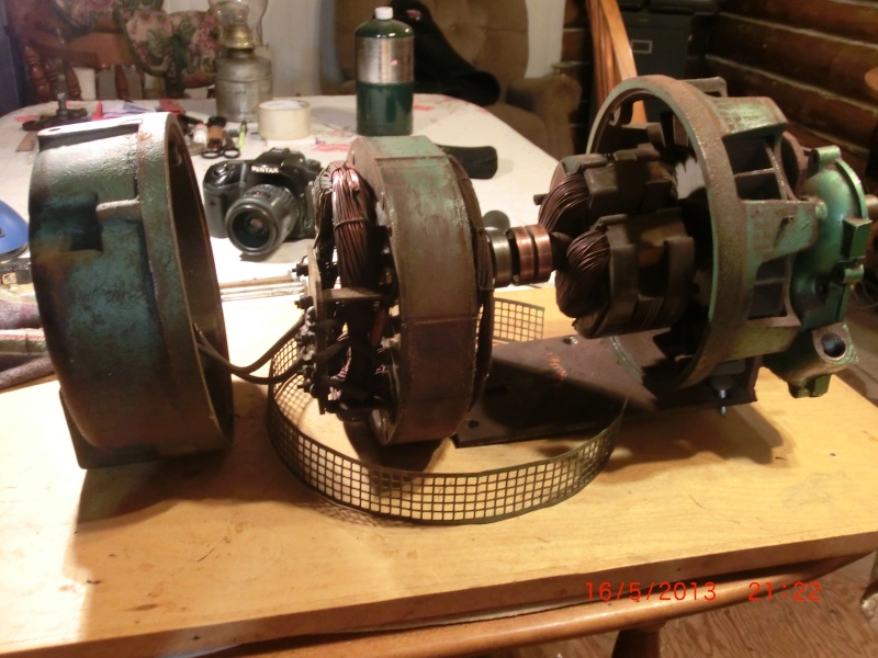
I have the genny apart and in three major sections, you can see the engine case to the right which needs to go away.
I know some of you have been there and tried to do the same thing, but I can't remember if you succeeded or not.
I have little time left to search so I will just finish up here and call it a day.
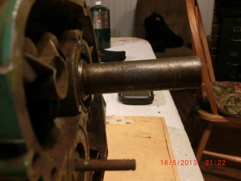
The engine end is what this post is about, and I need to find out what rotation may be needed to unscrew the outer shaft from the main rotor looking at it from the case end.
The assembly is an odd looking affair with the main shaft in two pieces and put together as one unit with the case inbetween that as a bearing boss and intregal. Meaning I have to take the case off and machine up a new boss to replace the case with so it can become a normal clean end to love and hold dear, and also to put a narrower pulley on to keep things streamlined. :chin:
I like things straight and clean looking and can't abide a messy engine case holding up the show!
Has any of you an idea weather to go CC or CW to unscrew the outer shaft end? When I pull on the other 4000 watt genny's pullcord, it rotates to CW to start it, so naturally it would un-screw to the opposite I think which would be CC., unless the end in the rotor is a taper held by the bolt that was removed from the other end of the shaft. (confusing isn't the word for it!)
It is the only way the assembly will come apart as the outer shaft has a ridge on it over which the bearing will not slide, and thus will not allow me to remove the case.
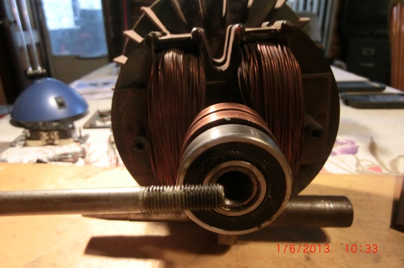
The outer shaft is inserted through the bearing (which houses in the case boss,) then through the case and the mounting bracket that someone made and then through the generator case and screwed onto the rotor on the inside of its windings which you see in this next picture.

The shaft here comes from the right trhough the case, bracket and gen case and is fastened inside the wound rotor and then bolted from the left (you can see the bolt head still in the shaft on the left in this pic,) straight through the center of the rotor to hold everything tight.
I can't see the reasoning to make things this difficult and complicated other than if it had to be some obscure means to save a few dollars on the manufacturing end of it.
Makes it so much harder for us tinkerers!
Anyway, the question stands.., does anyone have an idea as to how to unwind all of this mess so a good look can be had as to manufacturing a replacement bearing boss? Is there a possibility that the outer shaft is tapered and keyed inside the rotor, and held in by the anchor bolt on the left? That could make sense too and all it would need then is a good bump to make it come loose, sigh! I'm Tired and spent!!
Thanks all, good night and I'll see you on the road as I now have mobile internet in two countries lol.
Cheers, John.
The day is done and I need to get some rest as the slavery bell will toll for me in the morning to send me to Texas this time, and back up through Salt Lake for home. Be about a week and a half I guess.
Just quickly;
I have the genny apart and in three major sections, you can see the engine case to the right which needs to go away.
I know some of you have been there and tried to do the same thing, but I can't remember if you succeeded or not.
I have little time left to search so I will just finish up here and call it a day.
The engine end is what this post is about, and I need to find out what rotation may be needed to unscrew the outer shaft from the main rotor looking at it from the case end.
The assembly is an odd looking affair with the main shaft in two pieces and put together as one unit with the case inbetween that as a bearing boss and intregal. Meaning I have to take the case off and machine up a new boss to replace the case with so it can become a normal clean end to love and hold dear, and also to put a narrower pulley on to keep things streamlined. :chin:
I like things straight and clean looking and can't abide a messy engine case holding up the show!
Has any of you an idea weather to go CC or CW to unscrew the outer shaft end? When I pull on the other 4000 watt genny's pullcord, it rotates to CW to start it, so naturally it would un-screw to the opposite I think which would be CC., unless the end in the rotor is a taper held by the bolt that was removed from the other end of the shaft. (confusing isn't the word for it!)
It is the only way the assembly will come apart as the outer shaft has a ridge on it over which the bearing will not slide, and thus will not allow me to remove the case.
The outer shaft is inserted through the bearing (which houses in the case boss,) then through the case and the mounting bracket that someone made and then through the generator case and screwed onto the rotor on the inside of its windings which you see in this next picture.
The shaft here comes from the right trhough the case, bracket and gen case and is fastened inside the wound rotor and then bolted from the left (you can see the bolt head still in the shaft on the left in this pic,) straight through the center of the rotor to hold everything tight.
I can't see the reasoning to make things this difficult and complicated other than if it had to be some obscure means to save a few dollars on the manufacturing end of it.
Makes it so much harder for us tinkerers!
Anyway, the question stands.., does anyone have an idea as to how to unwind all of this mess so a good look can be had as to manufacturing a replacement bearing boss? Is there a possibility that the outer shaft is tapered and keyed inside the rotor, and held in by the anchor bolt on the left? That could make sense too and all it would need then is a good bump to make it come loose, sigh! I'm Tired and spent!!
Thanks all, good night and I'll see you on the road as I now have mobile internet in two countries lol.
Cheers, John.
_________________
Time is Nature's way of not having everything happen all at once.
It proves out because when everything happens all at once there's never enough time to deal with it!
Smitty- A credit to the forum
- Posts : 275
Join date : 2013-01-13
Age : 72
Location : North Bay, ON, Canada.
Re: Dayton Generator to play with.
![]() by nutgone Wed May 22 2013, 00:00
by nutgone Wed May 22 2013, 00:00
Ooooh, interesting! Might be a bit big or the Lister, but you're unlikely to fully load it anyway.
I will be watching with interest (as I was once an electrician, but never had much to do with generators, but I do have a good understanding of most things electrical).
Best of luck, try not to electrocute yourself!
I will be watching with interest (as I was once an electrician, but never had much to do with generators, but I do have a good understanding of most things electrical).
Best of luck, try not to electrocute yourself!
_________________
The "F" key is dying on my computer, please remember this when reading my posts, I'm trying to avoid using it.
The name's Matt, but call me Nutts if you like, there's already enough Matt's about.

nutgone- Life Member
- Posts : 2356
Join date : 2012-07-04
Age : 44
Location : East Sussex
Re: Dayton Generator to play with.
![]() by Smitty Fri May 24 2013, 22:56
by Smitty Fri May 24 2013, 22:56
nutgone wrote:Ooooh, interesting! Might be a bit big or the Lister, but you're unlikely to fully load it anyway.
I will be watching with interest (as I was once an electrician, but never had much to do with generators, but I do have a good understanding of most things electrical).
Best of luck, try not to electrocute yourself!
Hey Nut,
I'm having fun with it and want to accomplish what have in mind for it.
A mate for either the "D" or the IHC "Pig". Or any other old engine I may get in the future (No doubt I will!)
After doing some more searching I've found that it isn't as old as I'm thinking, but round the mid 60's to mid 70's.
But the construction is meant to last like the old school ones, so she's in!
I've tried to come up with a shematic or a blow up of the works for it, but no luck. I did however find that most of the engine genny's are assembled in a similar fashion, and once I decide I know what I'm doing, I'll attempt to take the rotor apart.
I forgot that I have a "ready to run" 10hp Briggs hiding in a corner somewhere to hook to it should it require more than the old engines can give to generate the stated 1Kw.
Is this thread in the right place or should it go to the shed maybe? This generator will be completed with an engine to go on, so I thought it might be ok here.
I'm sure l'll have my shock or two by time I finish this project lol, but I've trained since a little boy and immune to torture of that kind lol.
Regards, John.
_________________
Time is Nature's way of not having everything happen all at once.
It proves out because when everything happens all at once there's never enough time to deal with it!
Smitty- A credit to the forum
- Posts : 275
Join date : 2013-01-13
Age : 72
Location : North Bay, ON, Canada.
Re: Dayton Generator to play with.
![]() by Guest Sat May 25 2013, 12:39
by Guest Sat May 25 2013, 12:39
The threads ok here John, I know it's not an engine but it is still a resoration that could possibly help others in the future.
Good luck with it's overhaul and can't wait to see it making one of your engines work for it's keep.
Stu.
Good luck with it's overhaul and can't wait to see it making one of your engines work for it's keep.
Stu.
Guest- Guest
Re: Dayton Generator to play with.
![]() by Smitty Sun May 26 2013, 01:10
by Smitty Sun May 26 2013, 01:10
stationary stu wrote:The threads ok here John, I know it's not an engine but it is still a resoration that could possibly help others in the future.
Good luck with it's overhaul and can't wait to see it making one of your engines work for it's keep.
Stu.
Thanks Stu,
They are all going to be doing something for a livin! Power goes out here like we arnt worthy! So I have backups.
No reason to not have this 1K one working. I don't use a big draw on the system and only need a marginal backup for lights which this genny is perfect for.
I have the 4Kw one for the house at present should the electricity go for a dump longer than a few hours (which it does a few times in Winter)
The only big startup draws I have are the fridge and waterpump. The rest is propane or solar assisted lights, a separate stand-alone lighting circuit with charged batteries. (I like to mess with things
Regards, John.
_________________
Time is Nature's way of not having everything happen all at once.
It proves out because when everything happens all at once there's never enough time to deal with it!
Smitty- A credit to the forum
- Posts : 275
Join date : 2013-01-13
Age : 72
Location : North Bay, ON, Canada.
Re: Dayton Generator to play with.
![]() by Guest Sun May 26 2013, 12:57
by Guest Sun May 26 2013, 12:57
Sounds like you have everything covered for a blackout. It will be good to see these engines earn there keep again even if it's only for a day or 2 every Winter.
Stu.
Stu.
Guest- Guest
Re: Dayton Generator to play with.
![]() by Smitty Sat Jun 01 2013, 18:31
by Smitty Sat Jun 01 2013, 18:31
Back at it!
I took some more pics of the rotor assembly as I worked on it and thought I may as well explain how it works as I have never seen anything like this one, and some of you may benefit.
Got a big hammer out and was going to make it obey.., one blow (not a hard one ) and it separated from the rotor. I had to turn up a snug fitting drift to go through the rotor half which would not flatten the threaded hole end of the shaft taper and it worked a treat, the shaft popped out easy and no damage
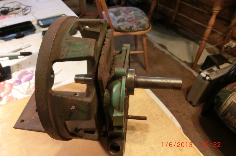
So when it came apart, that then allowed me to unbolt everything in the drive end and left me with the shaft and engine casing, for which I need to make a substitute bearing boss to be bolted to the mount that supports the genny as a stand alone, and thereby omitting the casing for a more practical and versatile genny and also esthetics. A nice flat belt pulley would do well for looks.

What surprised me was that there IS no key, only a tapered end, drilled and threaded for the bolt that draws it tight with the rotor in between.
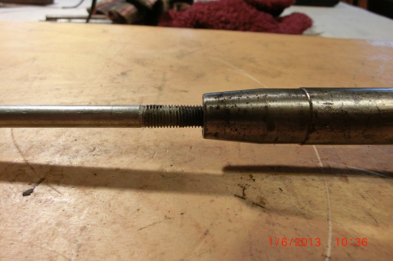
This is the end on the rotor where the bolt goes through and meets up with the inserted taper so it then draws the assembly together and becomes one piece with the drive end through the new boss and bearing, so a pully can then just be added and configured for 3600 rpm with what ever engine will drive it.
It is a strange (to me) design, but now that it has been apart I can see the practical sense in it as this is a convertible set up that can be used in a few different configurations at the drive end and leaves the general innards the same other than the drive end shaft. It can be suited for a few different styles of casing and also left alone for a straight input shaft, which is what I am attempting to accomplish here.

It is rather a tight setup once it is assembled and should do well for what I am doing with it after it has been altered.
It will never work overtime in my posession, and even if it had to it will serve without a problem I think.
Hope that helps for making it a bit clearer as to how this is assembled, Thx,
Regards John.
I took some more pics of the rotor assembly as I worked on it and thought I may as well explain how it works as I have never seen anything like this one, and some of you may benefit.
Got a big hammer out and was going to make it obey.., one blow (not a hard one
So when it came apart, that then allowed me to unbolt everything in the drive end and left me with the shaft and engine casing, for which I need to make a substitute bearing boss to be bolted to the mount that supports the genny as a stand alone, and thereby omitting the casing for a more practical and versatile genny and also esthetics. A nice flat belt pulley would do well for looks.
What surprised me was that there IS no key, only a tapered end, drilled and threaded for the bolt that draws it tight with the rotor in between.
This is the end on the rotor where the bolt goes through and meets up with the inserted taper so it then draws the assembly together and becomes one piece with the drive end through the new boss and bearing, so a pully can then just be added and configured for 3600 rpm with what ever engine will drive it.
It is a strange (to me) design, but now that it has been apart I can see the practical sense in it as this is a convertible set up that can be used in a few different configurations at the drive end and leaves the general innards the same other than the drive end shaft. It can be suited for a few different styles of casing and also left alone for a straight input shaft, which is what I am attempting to accomplish here.
It is rather a tight setup once it is assembled and should do well for what I am doing with it after it has been altered.
It will never work overtime in my posession, and even if it had to it will serve without a problem I think.
Hope that helps for making it a bit clearer as to how this is assembled, Thx,
Regards John.
_________________
Time is Nature's way of not having everything happen all at once.
It proves out because when everything happens all at once there's never enough time to deal with it!
Smitty- A credit to the forum
- Posts : 275
Join date : 2013-01-13
Age : 72
Location : North Bay, ON, Canada.
Re: Dayton Generator to play with.
![]() by nutgone Sun Jun 02 2013, 00:10
by nutgone Sun Jun 02 2013, 00:10
Was it direct coupled at some point? I've found this on a couple of generators recently & it seems to be common practise for direct coupled units these days.
That way they can usually get away with no bearing on the engine side of the genny, instead relying on the engines crank shaft bearing to do the job (on smaller units at least).
That's how they do it on all smaller ones these days anyway. I think I've got a thread in the resto section about a "Goodenough" generator of the same design. I need to purchase a bearing in a 4 hole flange mounting for the drive end & I had to get a tapered & threaded shaft, with a pulley on it, made up to go in there.
I really must get that bearing flange & finish that damn thing!
Good to see you back & on the case anyway.
_________________
The "F" key is dying on my computer, please remember this when reading my posts, I'm trying to avoid using it.
The name's Matt, but call me Nutts if you like, there's already enough Matt's about.
nutgone- Life Member
- Posts : 2356
Join date : 2012-07-04
Age : 44
Location : East Sussex
Re: Dayton Generator to play with.
![]() by nutgone Sun Jun 02 2013, 00:14
by nutgone Sun Jun 02 2013, 00:14
Sorry John, reading back of course it was direct coupled, it still has the engine crank case with the bearing in it!
I'm told they should have something fitted (like a screwed down plate or a circlip machined into the bearing housing) to stop any end-float. I know it's unlikely with a press fit bearing, but I'm told they can work themselves out & cause rotor damage in time. (Ian got in touch with a bloke who's converted a few to belt drive, he made the shaft attachment & did one for Ian as well, think there's a thread for that somewhere too).
I'm told they should have something fitted (like a screwed down plate or a circlip machined into the bearing housing) to stop any end-float. I know it's unlikely with a press fit bearing, but I'm told they can work themselves out & cause rotor damage in time. (Ian got in touch with a bloke who's converted a few to belt drive, he made the shaft attachment & did one for Ian as well, think there's a thread for that somewhere too).
_________________
The "F" key is dying on my computer, please remember this when reading my posts, I'm trying to avoid using it.
The name's Matt, but call me Nutts if you like, there's already enough Matt's about.
nutgone- Life Member
- Posts : 2356
Join date : 2012-07-04
Age : 44
Location : East Sussex
Re: Dayton Generator to play with.
![]() by Smitty Sun Jun 02 2013, 03:49
by Smitty Sun Jun 02 2013, 03:49
nutgone wrote:Sorry John, reading back of course it was direct coupled, it still has the engine crank case with the bearing in it!
I'm told they should have something fitted (like a screwed down plate or a circlip machined into the bearing housing) to stop any end-float. I know it's unlikely with a press fit bearing, but I'm told they can work themselves out & cause rotor damage in time. (Ian got in touch with a bloke who's converted a few to belt drive, he made the shaft attachment & did one for Ian as well, think there's a thread for that somewhere too).
Yes there is a thread or two some where Nut, I read it and the other when I first rolled in the door here.
No surprise it was you then lol.
Using the engine brearing is correct, that was the case with this one, and a good money saver I suppose.
TWO keeper clips (circlips) to hold the race from walking out (why two? I have no idea unless this tapered shaft is a homie), I don't think it is a press fit but just an interference fit as it is an Aluminium case, so a pressure fit would not be Ideal? Just guessing.
Ahh... :doh: , I see.., The clips hold the shaft in place as the engine is not there anymore to stop it from working loose!
I already have a steel split collar made up for another lost project, which is close to the size for the bearing outer race, so I may as well use that and drill 4 holes in it and fit it to the ratty but very usable mount that some one made up before Moi.
That leaves me the opportunity to tighten the bearing hole should it wear a bit in the future.
I can clean that ratty mount up and make it look like it belongs so why not?
It will be a nice thing to be able to switch engines at will, and that will guarantee it to be a keeper I think.
Of course I still need to find out if all of this is for naught, as I have not had the genny running to check it!
I'm testing my faith.., there's no fried wires anywhere nor discolored and darkened ones and everything looks peachy in there so I took the chance and started the work, I'll let you know if that was wrong after
That's Dutch impatience at work, but what the hey, I'm having fun at prices I can afford! Unlike the pickup truck which just cost me a whole day of life to fix never mind the bits I had to buy, but I got it done and it seems ok now, so off to do the chores I need the truck for. (engine hauling and mopeds, bikes, auto's (I built a car hauler one time and still use it
I'll keep you posted with any progress and shocks, electrocutions will be reported much later
John.
_________________
Time is Nature's way of not having everything happen all at once.
It proves out because when everything happens all at once there's never enough time to deal with it!
Smitty- A credit to the forum
- Posts : 275
Join date : 2013-01-13
Age : 72
Location : North Bay, ON, Canada.
Page 1 of 1
Permissions in this forum:
You cannot reply to topics in this forum