The most exhausting Scott
+3
Robotstar5
blue cat
maryalice
7 posters
Page 1 of 1
 The most exhausting Scott
I've recently started to work on a Scott generating set and I've now got to the point where I am able to get on with the clean-up and preparation phase of the restoration. The set has already been disassembled into smaller manageable lumps, making it easier to work on. The main base plate will need some welding before I am able to continue with that area, so while I wait for that to be completed, I decided I would move onto something smaller and easier, or so I thought. In most cases the exhaust system on small single cylinder engines are simple and consist of an exhaust pipe, clamp, brackets and usually but not always a silencer. In the case of the Scott, the designers have taken exhaust system design to a new level.
Once I had collected all the parts together, ready to clean them up, I realised this must be the most complex exhaust system ever, especially for a small single cylinder engine. It is made up of over twenty component parts, not including the flexible exhaust hoses usually associated with these sets. In addition there are the studs, nuts, washers and gaskets, which if you include all of those, the individual parts, number well in excess of 100. The design of the complete generating set seems to put quietening high on the priority list, with a very large and complex induction silencer on the carburettor, vibration mounts and the exhaust system, seemingly being over engineered, for what was a wartime generator for the sole use of powering the aiming and tracking capability of an anti-aircraft gun. I really don't think the attacking aircraft could have heard the generators operating from 1000 feet and I don't suppose the generator running would have worried the local population, as I imagine the noise of the bombs going off and the guns firing would have drowned out any generator noise! So why design something quite so complicated and therefore expensive during a wartime period? I can only assume the contract specification that the sets were built to, called for an arbitrary limit on the noise level, for what ever reason and this was how they met the design obligation.

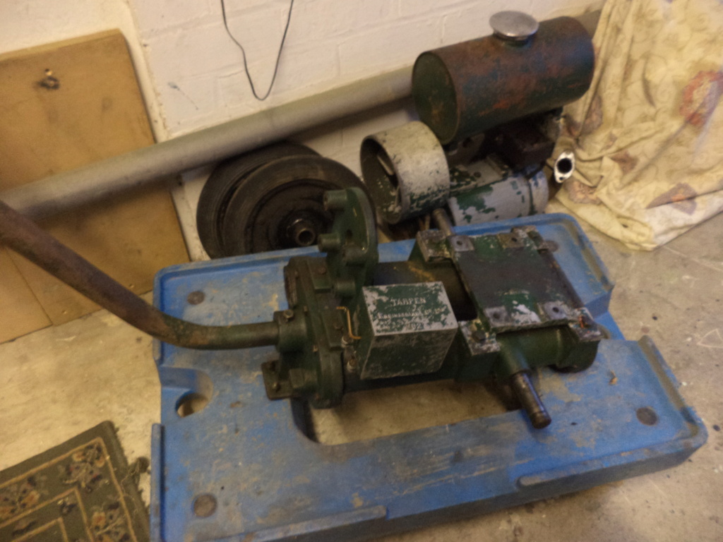
The starting point.
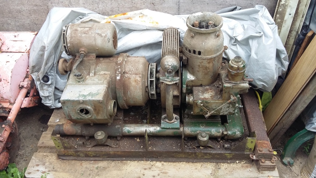
Engine base plate separated from the instrument and control desk, showing the engine and exhaust system.
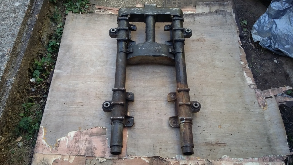
Underside of the lower section of the exhaust system prior to clean-up.

Exhaust components laid out prior to being prepared for painting.

Complete exhaust system bolted together, to demonstrate the complex design. The three horizontal pipes also have internal baffle mesh inside them.

Main exhaust tubes cleaned ready for painting.

And don't forget to look for any nuts that may have been lost under the engine, when you take it apart! Luckily there is no rodent damage to any of the generating electrics.
Once I had collected all the parts together, ready to clean them up, I realised this must be the most complex exhaust system ever, especially for a small single cylinder engine. It is made up of over twenty component parts, not including the flexible exhaust hoses usually associated with these sets. In addition there are the studs, nuts, washers and gaskets, which if you include all of those, the individual parts, number well in excess of 100. The design of the complete generating set seems to put quietening high on the priority list, with a very large and complex induction silencer on the carburettor, vibration mounts and the exhaust system, seemingly being over engineered, for what was a wartime generator for the sole use of powering the aiming and tracking capability of an anti-aircraft gun. I really don't think the attacking aircraft could have heard the generators operating from 1000 feet and I don't suppose the generator running would have worried the local population, as I imagine the noise of the bombs going off and the guns firing would have drowned out any generator noise! So why design something quite so complicated and therefore expensive during a wartime period? I can only assume the contract specification that the sets were built to, called for an arbitrary limit on the noise level, for what ever reason and this was how they met the design obligation.

The starting point.

Engine base plate separated from the instrument and control desk, showing the engine and exhaust system.

Underside of the lower section of the exhaust system prior to clean-up.

Exhaust components laid out prior to being prepared for painting.

Complete exhaust system bolted together, to demonstrate the complex design. The three horizontal pipes also have internal baffle mesh inside them.

Main exhaust tubes cleaned ready for painting.

And don't forget to look for any nuts that may have been lost under the engine, when you take it apart! Luckily there is no rodent damage to any of the generating electrics.
neil (LE)- A credit to the forum

- Posts : 399
Join date : 2012-03-21
Age : 68
Location : N/W Kent
 Re: The most exhausting Scott
My first thought was why is he showing a set of front forks off a motor bike.
Maryalice
Maryalice
maryalice- Life Member

- Posts : 1310
Join date : 2010-01-23
Age : 70
Location : Bedfordshire
 Re: The most exhausting Scott
Yes indeed they do look rather like motorbike forks. I've heard of oil in frame bikes before but I'm not aware of any exhaust in frame designs, unless you know different. I'm sure someone will!
Neil.
Neil.
neil (LE)- A credit to the forum

- Posts : 399
Join date : 2012-03-21
Age : 68
Location : N/W Kent
 Re: The most exhausting Scott
I don't know why the exhaust system is so elaborate, but a 4.5hp two-stroke running at 3000 rpm was always going to be a bit of a screamer 
_________________
blue cat
blue cat- Life Member

- Posts : 1065
Join date : 2013-10-10
 Re: The most exhausting Scott
They do sound good ticking over.
IIRC there was another cast bit to go over the end exit to for 2 into 1.
IIRC there was another cast bit to go over the end exit to for 2 into 1.
StuartTurnerSteve- Life Member

- Posts : 534
Join date : 2020-01-02
 Re: The most exhausting Scott
neil (LE) wrote:Yes indeed they do look rather like motorbike forks. I've heard of oil in frame bikes before but I'm not aware of any exhaust in frame designs, unless you know different. I'm sure someone will!
Neil.
How about "air in frame"?, I have a Villiers powered compressor set that uses the frame tubing as a receiver...

_________________
Stuart
Robotstar5- Life Member

- Posts : 1109
Join date : 2018-09-25

mattblack- Life Member

- Posts : 889
Join date : 2019-06-21
Location : Leicester, me duck...
 Re: The most exhausting Scott
Hi Steve, if you mean on the end of the two lower longitudinal exhaust pipes, then I don't believe there was a cast item on those. The two pipes actually extend through and beyond the end cover panel and have internal threads in them to accommodate the flexible extension exhaust hoses. There are two flexible pipes shown in pictures which I have seen, which also show the large union nuts external to the unit which attach the pipes. If anybody has a set of extension exhaust hoses and union nuts that they want to sell, then I would be interested. I don't hold out much hope but you never know.
Work has continued cleaning up all the parts of the exhaust system, ready for painting. If the weather is reasonable and I get time, a start could be made on priming the various items. A number of the components are aluminium or bronze castings, so I will be using an acid etch primer, which also happens to be heat resistant which will be useful on the exhaust system.

Most of the exhaust system cleaned up and prepared for priming. Note the short pipe still in Olive Drab which will be the final colour.
Work has continued cleaning up all the parts of the exhaust system, ready for painting. If the weather is reasonable and I get time, a start could be made on priming the various items. A number of the components are aluminium or bronze castings, so I will be using an acid etch primer, which also happens to be heat resistant which will be useful on the exhaust system.

Most of the exhaust system cleaned up and prepared for priming. Note the short pipe still in Olive Drab which will be the final colour.
neil (LE)- A credit to the forum

- Posts : 399
Join date : 2012-03-21
Age : 68
Location : N/W Kent
 Re: The most exhausting Scott
Stuart, Matt, I knew there would be some interesting uses of engine frames. Innovation by designers looking to ensure maximum use of space and build economies bring out some interesting ideas! So far we have exhaust, oil, air, using the frame. I imagine there will be some using the frame for fuel and maybe coolant, not that I know of any but I imagine someone will.
Neil.
Neil.
neil (LE)- A credit to the forum

- Posts : 399
Join date : 2012-03-21
Age : 68
Location : N/W Kent
 Re: The most exhausting Scott
Oh right, I'm sure I read somewhere there was a 2-1 attachment. Mine wasn't threaded to accept any extensions.
StuartTurnerSteve- Life Member

- Posts : 534
Join date : 2020-01-02
 Re: The most exhausting Scott
neil (LE) wrote:(snip) I've heard of oil in frame bikes before but I'm not aware of any exhaust in frame designs, unless you know different. I'm sure someone will!
Neil.
Including early Scott motorcycles of course. Oh, and Morgan three-wheelers used their chassis tubes as exhaust pipes!
I believe that when the Ministry put out the initial request for tender it was envisaged that the Bofors / Kerrison set would be used in mobile and potentially forward positions, so was required to be highly portable and sufficiently well silenced to not attract enemy ground fire. As is often the way with military equipment, requirements changed rapidly and most Bofors emplacements were ultimately relatively static and well back from the front line, as a result of which the less portable Coventry Climax gen sets were preferred.

nickh- Expert

- Posts : 56
Join date : 2019-04-14
 Re: The most exhausting Scott
I thought somebody would know a manufacturer who used the chassis as part of the exhaust system, I just didn't imagine it would be the Scott motorcycle company!
It seems that it was expected use of the generators in a forward position which required the quietening of the sets. I also remember reading somewhere that it was both the Kerrison predictor and the generator that were too cumbersome to move around which meant that most of the Kerrison equipped Bofors guns ended up in static positions. However as the design required the sets to be mobile, Scott's design met this obligation by the simple expediency of fitting hollow tubes along the top of the frame, into which were inserted "standard porter bars" which were held in place with pins chained to the top of the instrument table. It was expected that four service personnel would then be able to move the unit around. However I don't believe they would have been able to move it very far, as the weight of the unit would have tested the strength of any of the military's finest. I don't actually know the weight of a complete set but I have estimated it at somewhere between 250 - 350Kgs. If anyone does know the weight, then please let me know, as it would be very useful to find out.

Diagram showing the "standard porter bars" in place. Also shown are the flexible exhaust extension pipes and connecting union nuts.
It seems that it was expected use of the generators in a forward position which required the quietening of the sets. I also remember reading somewhere that it was both the Kerrison predictor and the generator that were too cumbersome to move around which meant that most of the Kerrison equipped Bofors guns ended up in static positions. However as the design required the sets to be mobile, Scott's design met this obligation by the simple expediency of fitting hollow tubes along the top of the frame, into which were inserted "standard porter bars" which were held in place with pins chained to the top of the instrument table. It was expected that four service personnel would then be able to move the unit around. However I don't believe they would have been able to move it very far, as the weight of the unit would have tested the strength of any of the military's finest. I don't actually know the weight of a complete set but I have estimated it at somewhere between 250 - 350Kgs. If anyone does know the weight, then please let me know, as it would be very useful to find out.

Diagram showing the "standard porter bars" in place. Also shown are the flexible exhaust extension pipes and connecting union nuts.
Last edited by neil (LE) on Fri Oct 02 2020, 21:24; edited 1 time in total (Reason for editing : corrected wording.)
neil (LE)- A credit to the forum

- Posts : 399
Join date : 2012-03-21
Age : 68
Location : N/W Kent
 Re: The most exhausting Scott
Sorry, I worded that badly - Scott was oil in frame, Morgan 'zorst in frame!
Last edited by nickh on Fri Oct 02 2020, 20:35; edited 1 time in total

nickh- Expert

- Posts : 56
Join date : 2019-04-14
 Re: The most exhausting Scott
Thanks for that, still interesting though!
neil (LE)- A credit to the forum

- Posts : 399
Join date : 2012-03-21
Age : 68
Location : N/W Kent
 Re: The most exhausting Scott
Thanks for the photo.
StuartTurnerSteve- Life Member

- Posts : 534
Join date : 2020-01-02
 Scott went a little grey, now looking green and exhausted!
Hi, I've managed to find a little time to continue to work on the Scott's exhaust system, which initially went grey and then green. As I mentioned previously, I have used an acid etch primer, due to the aluminium and bronze cast parts and copper pipes. I have also used it on the steel items as well, as the primer is heat resistant and will hopefully provide a consistent base for the top coat. I found the primer went on quite well, although it did require a couple of coats but once applied provided a good hard smooth coverage. The top coat is a specialist military paint, Olive Drab to BS 381C 298 Matt finish. This, I found more difficult to apply, without ending up with the paint pulling and tearing, requiring the surface to be rubbed back a numbers of times and further layers of paint applied. Although I have achieved an acceptable finish, it is not exactly as I would like. Although the paint is a Matt finish, there is a satin sheen on the surface which means it doesn't look correct. This issue is identified by the supplier, as a means to prevent finger marks affecting the surface and the finish will matt down over time. It will be interesting to see how this actually works out. Has anybody used this paint or maybe a different supplier for authentic military colours?

Going grey. Special etch primer applied to the exhaust components.
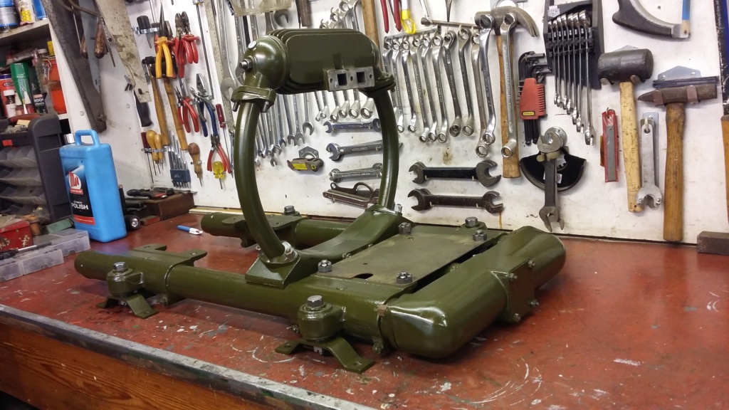
Now gone green. The exhaust system temporarily dry fitted together to get an idea of the overall look of the finish.

Rear view of the exhaust set up.

Paint details, indicating the initial satin finish.

Going grey. Special etch primer applied to the exhaust components.

Now gone green. The exhaust system temporarily dry fitted together to get an idea of the overall look of the finish.

Rear view of the exhaust set up.

Paint details, indicating the initial satin finish.
neil (LE)- A credit to the forum

- Posts : 399
Join date : 2012-03-21
Age : 68
Location : N/W Kent
 Re: The most exhausting Scott
FWIW I think the satin finish looks 'right' as it is. I would think under wartime production conditions there would be some variation in paint shade and level of 'mattness' anyway.
_________________
Specialist in precision guesswork.

mattblack- Life Member

- Posts : 889
Join date : 2019-06-21
Location : Leicester, me duck...
 Re: The most exhausting Scott
Cheers, there have been other comments in a similar vein. I think I will stick with it and see how it looks when completed, which may be some time yet!
Neil
Neil
neil (LE)- A credit to the forum

- Posts : 399
Join date : 2012-03-21
Age : 68
Location : N/W Kent
 Similar topics
» My New P & J, a Scott.
» Scott PAB Engine Strip-Down
» A Scott Testing Question
» great scott!
» Scott PAB Restoration
» Scott PAB Engine Strip-Down
» A Scott Testing Question
» great scott!
» Scott PAB Restoration
Page 1 of 1
Permissions in this forum:
You cannot reply to topics in this forum
